Pressure vessels that fail don’t just shut down operations; they cause injuries, damage equipment, and trigger regulatory investigations. The safety factor is the engineering margin built into every vessel design to prevent that outcome. This guide is for engineers, procurement managers, and plant operators who need to understand what the typical safety factor for pressure vessels is, how it’s calculated under ASME standards, and what variables change it in real applications.
What Is the Safety Factor in Pressure Vessel Design?
The safety factor, also called the design factor, is the ratio between a material’s ultimate tensile strength and the allowable stress used in vessel design calculations. It defines how much stronger the vessel is than the minimum required to contain its operating pressure.
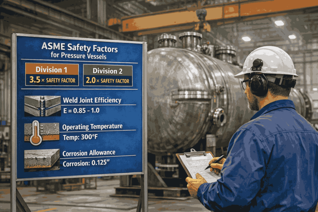
Under ASME Boiler and Pressure Vessel Code (BPVC) Section VIII Division 1, the standard safety factor is 3.5. This means the vessel is designed to withstand 3.5 times the stress it will experience under normal operating conditions before material failure is expected.
This margin accounts for uncertainties that cannot be fully controlled, such as material imperfections, weld quality variations, temperature fluctuations, and wear over time.
ASME Section VIII Division 1 vs Division 2 Safety Factors
The safety factor applied to a pressure vessel depends heavily on which ASME division governs its design.
- Division 1, Design by Rule: The safety factor is 3.5 for most materials. This conservative approach uses prescriptive formulas and tables to determine wall thickness and allowable stress without requiring detailed stress analysis. It’s the most widely used standard for general industrial applications.
- Division 2, Design by Analysis: Division 2 allows safety factors between 2.4 and 3.0, depending on the specific stress criteria being evaluated. Because it requires detailed finite element analysis and fatigue assessment, the reduced safety factor is backed by a more rigorous engineering process, not a relaxation of standards. For more on how the two divisions compare, see ASME Section VIII Division 1 vs Division 2.
The tradeoff is clear: Division 1 is faster and simpler to certify. Division 2 allows thinner, lighter vessels that cost less material to fabricate but require more engineering upfront.
How the Safety Factor Is Calculated
The basic calculation for allowable stress under ASME Division 1 is:
Allowable Stress (S) = Ultimate Tensile Strength ÷ 3.5
For example, if a carbon steel plate has an ultimate tensile strength of 70,000 psi, the allowable stress used in design calculations would be 20,000 psi. The vessel walls, nozzle reinforcements, and weld joints are all sized to keep actual stresses below that value.
ASME Section II Part D provides the approved allowable stress values for each material at specific operating temperatures. Designers reference these tables rather than calculating from tensile strength alone, as temperature affects material strength, and the allowable stress values already account for this.
Factors That Change the Effective Safety Factor
The nominal safety factor of 3.5 is a starting point, not a fixed value for every application. Several variables affect the actual safety margin of a completed vessel.
- Weld Joint Efficiency: Welds that are fully radiographed achieve a joint efficiency of 1.0, meaning the full allowable stress applies. Partially examined or uninspected welds carry efficiency values of 0.85 or 0.70, effectively reducing the allowable stress and requiring thicker walls to compensate. This is one of the most impactful variables in real fabrication.
- Corrosion Allowance: Vessels handling corrosive media are designed with additional wall thickness beyond the calculated minimum. This does not change the safety factor formula, but it increases the actual material margin built into the vessel at the start of its service life.
- Cyclic Loading and Fatigue: Vessels that experience repeated pressure cycles accumulate fatigue stress. Under Division 1, this is addressed through conservative design factors rather than explicit fatigue analysis. Division 2 requires a formal fatigue assessment, particularly for vessels that cycle frequently in gas-processing or compressed-air applications. For more on ASME code compliance in these applications, Red River’s engineering team can review your project specifications.
Operating Temperature: Material strength decreases at elevated temperatures. ASME Section II Part D tables provide reduced allowable stress values for high-temperature service, which automatically increases the required wall thickness when applied in design calculations.
Safety Factors in Practice: What Red River Applies
At Red River, every vessel we fabricate under ASME Section VIII Division 1 is designed to the 3.5 safety factor using only ASME-approved materials with documented mechanical properties and full traceability.
For clients in oil and gas, power generation, and industrial gas processing, we assess weld joint efficiency requirements early in the design phase because the decision to fully radiograph welds versus spot examine them affects both the safety margin and the final wall thickness, which in turn affects cost and delivery.
When a project calls for Division 2, our team conducts the required design-by-analysis before recommending the reduced safety factor, never as a cost-cutting shortcut, but as a calculated engineering decision backed by the code. ASME code-stamped vessels from Red River carry documentation through every stage of that process.
Need a Reliable Partner?
Red River designs and fabricates ASME U-stamp certified pressure vessels and modular skid packages under both Division 1 and Division 2. Our engineering team evaluates safety factor requirements, material selection, and weld joint efficiency for each project before fabrication begins. Contact our team to discuss your pressure vessel specifications.
Frequently Asked Questions
1. What is the typical safety factor for pressure vessels under ASME?
Under ASME Section VIII Division 1, the standard safety factor is 3.5 for most materials and applications. Division 2 allows lower safety factors between 2.4 and 3.0, but requires more rigorous stress analysis and fatigue assessment to justify the reduction.
2. Why is the ASME safety factor set at 3.5?
The 3.5 factor was established to account for uncertainties inherent in material properties, fabrication quality, and operating conditions that cannot be fully predicted. It provides a conservative margin that has proven reliable across decades of industrial pressure vessel operation.
4. Does the safety factor change with temperature?
Yes. ASME Section II Part D provides allowable stress values that decrease at higher temperatures, which effectively increases the wall thickness required at elevated operating temperatures. The formula remains the same, but the allowable stress input changes.
5. What is the difference between the safety factor and the design factor?
In pressure vessel engineering, these terms are often used interchangeably. Both refer to the ratio applied to material strength to determine the maximum allowable working stress used in design calculations.
6. How does weld joint efficiency affect the safety margin?
Weld joint efficiency reduces the allowable stress applied to welded joints depending on the level of radiographic examination performed. A fully examined weld achieves 100% efficiency. Spot-examined or uninspected welds use reduced efficiency values, which require thicker walls to maintain the required safety margin.
7. Can a vessel be designed with a lower safety factor than 3.5?
Yes, under ASME Division 2, safety factors as low as 2.4 are permitted for specific stress criteria but only when supported by design-by-analysis methods, including finite element analysis and fatigue assessment. Reducing the safety factor without that analysis is not code-compliant.
Key Takeaways
- The typical safety factor for pressure vessels under ASME Section VIII Division 1 is 3.5, meaning the vessel is designed to withstand 3.5 times its operating stress before material failure.
- ASME Division 2 allows reduced safety factors between 2.4 and 3.0, but requires detailed design-by-analysis and fatigue assessment to justify the reduction.
- Weld joint efficiency, operating temperature, corrosion allowance, and cyclic loading all affect the actual safety margin built into a completed vessel.
- ASME Section II Part D provides the approved allowable stress values for each material at specific temperatures. Designers reference these tables, not raw tensile strength alone.
- Red River fabricates ASME U-stamp certified vessels under both Division 1 and Division 2, with full engineering documentation from design through certification.
Related Blog Post
How Do You Size Thermal Storage for Data Centers?
Thermal Storage Tank Design Engineering
No subpillar set for this blog post.
About Author