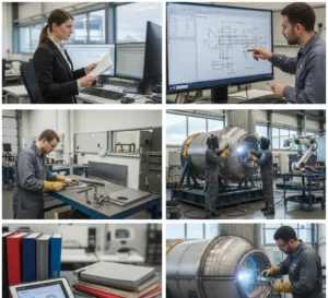
The CAD and FEA engineering role in OEM pressure vessel is foundational to modern manufacturing. These digital tools bridge the gap between concept and fabrication by enabling engineers to design, simulate, and validate vessels before a single piece of metal is cut. Whether optimizing wall thickness, predicting stress behavior, or ensuring compliance with ASME codes, CAD (Computer-Aided Design) and FEA (Finite Element Analysis) are essential in delivering safe, efficient, and cost-effective pressure vessels.
Understanding CAD and FEA Engineering Role
In modern pressure vessel engineering, CAD (Computer-Aided Design) and FEA (Finite Element Analysis) are no longer optional they are essential tools for ensuring accuracy, safety, and efficiency throughout the design and manufacturing process.
From initial geometry creation to simulation-driven optimization and fabrication planning, CAD and FEA help engineers deliver high-quality pressure vessels that meet industry codes and customer expectations.
Key functions of CAD in OEM vessel design:
CAD is the backbone of pressure vessel design. Engineers use it to create precise 2D and 3D models of every component shells, heads, nozzles, supports, and internal attachments. This enables:
- Accurate geometry and dimensions
- Optimized nozzle placement and layout
- Seamless integration with piping and instrumentation (P&IDs)
- Collaborative review across engineering, quality, and fabrication teams
This is why CAD is critical in pressure vessel engineering and pressure vessel manufacturing.
Key CAD Capabilities in OEM Vessel Design
- Shell and head modeling
- Nozzle and flange layout
- Internal component placement (baffles, coils, jackets)
- Supports, saddles, and mounting arrangements
- Fabrication-ready drawings for CNC and cutting
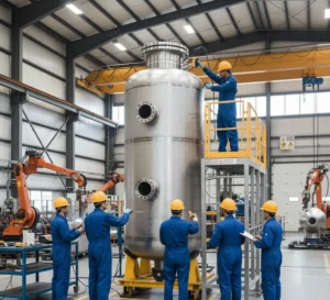
Learn more about metal fabrication and manufacturing process of pressure vessels.
The Power of Finite Element Analysis (FEA)
In addition to CAD, FEA plays a pivotal role by simulating how a pressure vessel behaves under operational loads, including pressure, heat, vibration, and external forces. Consequently, engineers can predict and address potential weaknesses before physical construction.
Applications of FEA in pressure vessel design:
- Stress and strain distribution analysis
- Buckling and deformation simulation
- Thermal gradient mapping
- Fatigue and lifecycle prediction
- Verification of reinforcement and support structures
By running FEA simulations, engineers can identify potential failure points and refine the design before fabrication begins. As a result, this process significantly reduces costly rework and enhances safety.
Benefits of CAD & FEA in OEM Pressure Vessel Engineering
The CAD, FEA engineering role in OEM pressure vessels brings measurable improvements in every project stage. In particular, these tools provide a variety of benefits that streamline the design and manufacturing processes.
Enhanced Design Accuracy
CAD eliminates manual drafting errors and ensures exact dimensions across complex assemblies. This is especially important in ASME-certified pressure vessels.
Code Compliance
Simulations help meet ASME, API, and customer-specific design codes with confidence.
Faster Project Turnaround
Digital workflows reduce design review cycles and prevent rework. This is key for prefabrication and modular skids.
Cost Efficiency
FEA identifies over-engineering or under-engineering early, saving material costs and fabrication delays. It also improves the quality of custom pressure tank manufacturing.
Better Communication
3D models and simulation reports help stakeholders from clients to fabrication teams understand the design intent and performance.
Explore more about pressure tanks vs pressure vessels and types of industrial pressure vessels.
Examples of Real-World Applications
The CAD, FEA engineering role in OEM pressure vessel design is especially critical in high-stakes industries such as oil and gas, chemical processing, aerospace, and power generation. In these sectors, pressure vessels must consistently withstand extreme temperatures, pressures, and corrosive environments leaving no room for design flaws or structural failure.
Aerospace
FEA ensures that fuel vessels maintain structural integrity under extreme conditions, such as rapid altitude pressure changes, thermal fluctuations, and continuous vibration. By simulating these operational stresses in a virtual environment, engineers can predict potential failure points, optimize design features, and validate material choices before manufacturing begins. This level of precision is especially vital in aerospace and defense applications, where even minor structural weaknesses can have critical consequences.
Biotech
CAD plays a crucial role in achieving tight-tolerance design for clean-in-place (CIP) vessels and sensitive mixing applications. In these systems, even minor dimensional inaccuracies can compromise hygiene, disrupt flow dynamics, or lead to cross-contamination. With CAD, engineers can precisely model internal geometries, nozzle placements, and surface finishes to ensure seamless integration with automated cleaning systems and maintain compliance with sanitary standards such as 3-A, ASME BPE and FDA standards. This precision is especially important in industries like pharmaceuticals, biotechnology, and food processing, where sterility and consistency are non-negotiable..
Energy
FEA models simulate long-term fatigue in pressure vessels exposed to thermal cycling, particularly in high-demand environments like nuclear and fossil fuel power plants. These vessels regularly undergo repeated heating and cooling cycles, which can cause material fatigue, stress cracking, and eventual structural failure if not properly addressed during the design phase. Finite Element Analysis enables engineers to model these thermal fluctuations over time, predict cumulative damage, and assess the vessel’s lifespan under real operating conditions. By identifying high-risk areas and optimizing design and material selection, FEA helps ensure long-term reliability, safety, and regulatory compliance in some of the most demanding industrial applications.
Chemical Processing
CAD ensures precise compatibility of pressure vessels with complex process piping systems, heat exchangers, and other integrated equipment. In large-scale industrial setups such as chemical plants, refineries, and pharmaceutical facilities pressure vessels must seamlessly connect with surrounding infrastructure to maintain flow efficiency, thermal performance, and system safety. Using CAD, engineers can develop detailed 3D assemblies that account for exact nozzle orientations, support structures, flange alignments, and spatial constraints. This level of precision minimizes fit-up issues during installation, reduces costly on-site modifications, and enhances the overall reliability of the process system.
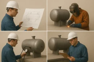
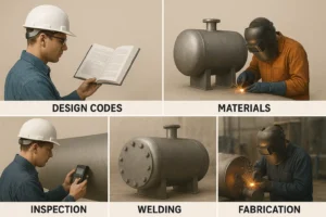
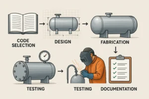
Integrating CAD & FEA in the Manufacturing Workflow
The CAD, FEA engineering role in OEM pressure vessel doesn’t stop at design it extends into every step of the fabrication process.
Integration steps:
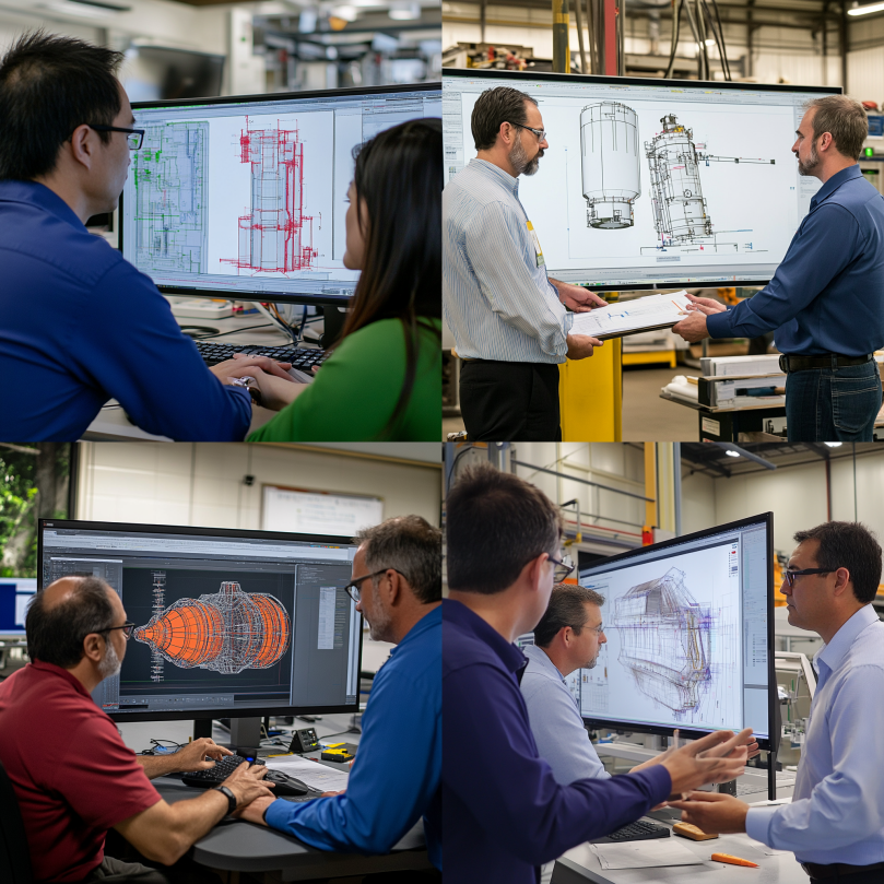
- CAD-to-CAM: CAD models feed directly into CNC machines for precise cutting and forming.
- Digital twins: FEA models create real-time simulations that match physical vessels for lifecycle management.
- Inspection and QA: Simulated tolerance checks ensure welded components match design intent.
- Documentation: Digital records meet compliance and traceability standards with ease.
Learn more about fabrication process: cutting, folding, welding.
Design Technology in Vessel CAD and FEA Engineering Role
The CAD, FEA engineering role in OEM pressure vessel design cannot be overstated. These advanced engineering tools have transformed the industry from a traditionally reactive process into one driven by proactive precision and innovation. By leveraging CAD (Computer-Aided Design), engineers can create highly detailed 3D models that accurately represent the physical and functional aspects of pressure vessels. FEA (Finite Element Analysis) takes this a step further by simulating real-world stress, load conditions, thermal effects, and structural integrity under various scenarios long before any physical prototype is built.
This integrated approach allows manufacturers to detect potential failure points, optimize material usage, and refine geometries to meet increasingly stringent industry codes and customer specifications. Every inch of the vessel can be digitally tested and perfected, reducing costly rework and ensuring performance predictability. As global industries push for higher efficiency, greater durability, and tighter safety margins, the CAD, FEA engineering role becomes even more critical. These technologies are no longer optional they are foundational to delivering safer, smarter, more scalable, and code-compliant OEM pressure vessel designs.
Need a reliable partner?
Red River specializes in the design and manufacturing of pressure vessels. We also fabricate related items such as prefabricated spools and skid packages.
Reach out to us today and experience the Red River difference. Where American-made products and American Values come together, we care more.
Frequently Asked Questions
1. What’s the difference between CAD and FEA in pressure vessel design?
CAD is used to create 3D models and drawings, while FEA simulates how those models respond to pressure, stress, and temperature.
2. Why is FEA important in OEM pressure vessel builds?
It ensures the vessel can withstand real-world operating conditions and prevents structural failures before manufacturing begins.
3. Can CAD and FEA reduce fabrication costs?
Yes. By optimizing material usage and preventing over-engineering, both tools help reduce waste and unnecessary expenses.
4. Are CAD and FEA required by code?
While not explicitly mandated, many ASME and API standards recommend or assume use of advanced design tools to validate complex structures.
5. Can CAD and FEA be used for retrofits or upgrades?
Absolutely. They’re valuable for redesigning existing systems, checking compatibility, and improving older vessels.
Key Takeaways
- The CAD, FEA engineering role in OEM pressure vessel drives design accuracy, code compliance, and performance validation.
- CAD models support dimensional precision, integration, and collaboration.
- FEA simulates stress, fatigue, thermal effects, and structural responses.
- These tools reduce costs, speed up production, and enhance lifecycle durability.
Related Blog Post
Pressure Vessel Design & Engineering: Concept to Launch
What is Pressure Vessel Design and Engineering: Code-Ready Guide
What are the Key Factors in Pressure Vessel Engineering
How Do You Design a Pressure Vessel: A Step-By-Step Guide