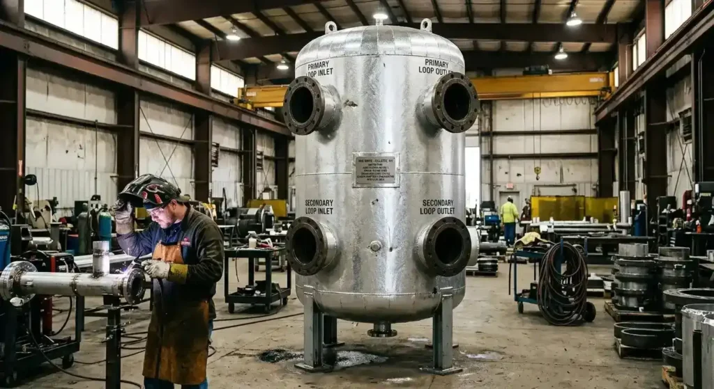
Hydronic tanks stabilize flow by hydraulically separating the heat source from the distribution system and adding thermal mass to the loop, so pumps and the boiler or chiller operate on steady, independent flow instead of competing against one another. The result is fewer pressure swings, less short cycling, and protection for every pump and valve downstream.
Key Takeaways
- Hydronic tanks stabilize flow mainly through hydraulic separation, which lets the source and the distribution loop run on independent flow rates without interfering with each other.
- A buffer tank adds thermal mass that smooths load swings and keeps the heat source from short cycling by giving it enough water volume to run complete, efficient cycles.
- Decoupling primary and secondary loops removes the flow interference that causes pressure swings, noise, and uneven heating or cooling across the system.
- Air and dirt separation protects flow by clearing the entrained bubbles and debris that foul pumps, cause cavitation, and create dead spots where flow stalls.
- A hydronic tank that stabilizes flow is a coded pressure vessel when it operates above 15 psig, designed to the specific loop’s pressure, temperature, and connection requirements.
How Do Hydronic Tanks Stabilize Flow in a System?
Hydronic tanks stabilize flow by doing two things at once: hydraulically separating parts of the system that would otherwise interfere, and adding stored volume that absorbs sudden changes in load. Together these convert a reactive, unstable loop into a steady one.
Why Pump Interference Causes Flow Problems
In a closed hydronic system, the heat source has its own pump and the distribution side has its own pumps, and those pumps do not always demand the same flow at the same time. Without a buffer between them, one side’s demand pulls against the other, creating pressure swings and uneven delivery across the facility.
How the Tank Resolves the Conflict
A hydronic tank placed between the source and distribution circuits gives the flow a common, low-resistance point to meet. Each side draws what it needs without disturbing the other. The added thermal mass does the rest: a larger volume of water changes temperature slowly, so a brief load spike does not force the boiler or chiller to react instantly. That damping keeps flow and temperature stable across the full loop.
What Is Hydraulic Separation and Why Does It Matter?
Hydraulic separation is the engineering principle that allows two connected pumping circuits to operate without forcing flow on each other. It is the single most important mechanism through which hydronic tanks stabilize flow, and it is determined by how the tank is piped into the system.
Decoupling Primary and Secondary Loops
Most larger hydronic systems split into a primary loop serving the heat source and one or more secondary loops serving the building zones. When those circuits connect directly, a change in flow on one side immediately disturbs the other. A buffer tank or hydraulic separator placed at the junction decouples them, so the source pump and the distribution pumps each see stable, independent flow conditions.
Low-Loss Headers vs. Buffer Tanks
A low-loss header and a buffer tank both create a zone of near-zero pressure drop where primary and secondary flow can exchange freely. The difference is volume. A buffer tank adds significant thermal mass alongside the separation point, which is why it is the preferred choice on low-mass systems that also need to prevent rapid on-off cycling of the heat source. ASHRAE publishes guidance on sizing hydraulic separation components for hydronic systems.
How Does Added Volume Prevent Short Cycling?
Short cycling occurs when a heat source starts and stops too frequently because the loop holds too little water to absorb its output. Each start-stop cycle wastes energy, accelerates mechanical wear, and sends pulses of changing flow through the system that destabilize temperatures downstream.
How the Buffer Tank Solves It
A buffer tank solves short cycling by adding water volume the source can heat or cool across longer, steadier cycles. With enough thermal mass in the loop, the chiller or boiler completes full cycles instead of rapid on-off bursts, smoothing both its energy use and the flow it delivers.
How Volume Is Calculated
The correct buffer volume comes from two inputs: the source’s minimum run time and the smallest anticipated system load. Both are confirmed during the design phase. Red River works through these sizing inputs before the fabrication scope is set. See Red River’s thermal energy storage and process tanks pages for related vessel types used across closed-loop systems.
How Do Air, Dirt, and Pressure Stability Affect Flow?
Flow stability depends on more than pump sizing and vessel volume. The condition of the fluid and the steadiness of loop pressure each shape how consistently water moves through the system.
Air and Dirt Separation
Entrained air is a common and underestimated flow disruptor. Bubbles collect at high points and in pump volutes, causing noise, cavitation, and dead spots where flow stalls entirely. An air and dirt separator slows fluid velocity enough for bubbles to rise out and suspended particles to settle, clearing the obstructions that make flow erratic and protecting downstream pumps and heat exchangers.
Pressure Stability Through the Expansion Tank
As water heats and cools, it expands and contracts. An expansion tank absorbs that volume change and holds loop pressure within a safe operating band. A loop with stable pressure delivers stable flow. These functions, combined with buffering and separation, are part of the pressure vessel fabrication and capabilities Red River applies to complete hydronic vessel scopes.
Where Does Flow Stability Matter Most?
Flow stability matters most wherever loads change quickly or where temperature precision is a hard requirement.
Power Generation and Industrial Process
Power generation and combined heat and power plants rely on stable hydronic flow to match heat production to variable demand. Industrial process facilities depend on consistent temperature delivery to maintain process conditions within specified limits. Both applications benefit from properly sized buffer and storage vessels integrated into modular skid packages that arrive pre-piped and pre-tested.
Commercial and Institutional Buildings
Commercial buildings, hospitals, campuses, and manufacturing plants benefit from the steadier operation a well-sized hydronic tank provides. In many settings the vessel is integrated into a pre-tested skid assembly that reduces field installation scope.
What This Means When Specifying a Hydronic Tank
How hydronic tanks stabilize flow comes down to three mechanisms working together: hydraulic separation that decouples the source from the distribution side, thermal mass that prevents short cycling, and clean pressure-stable fluid that carries flow without interruption. Specifying the wrong tank type, or the right type at the wrong size, produces the instability the tank was intended to eliminate. Those decisions belong in the design phase, confirmed against the specific loop before fabrication begins.
Discuss Flow Stability and Hydronic Tank Fabrication With Red River
Red River has fabricated ASME-certified hydronic and buffer tanks for power generation, industrial process, and commercial applications from Gillette, Wyoming, since 2003. Red River holds active ASME U Stamp and NBBI R Stamp certifications and is an American Welding Society (AWS) member. Request a quote or call us to discuss your tank type, sizing inputs, and fabrication scope.
Frequently Asked Questions
1. What Is Hydraulic Separation in a Hydronic System?
Hydraulic separation is a piping arrangement that lets two pumped circuits operate without forcing flow on each other. A buffer tank, hydraulic separator, or low-loss header creates a low-resistance zone where the primary and secondary loops can meet and exchange flow. This keeps the heat source and the distribution pumps on stable, independent flow conditions.
2. How Does a Buffer Tank Stop Short Cycling?
The tank adds water volume so the heat source can run in longer, steadier cycles instead of rapid on-off bursts. Short cycling occurs when the loop holds too little water to absorb the source’s output. The added thermal mass gives the chiller or boiler the volume it needs to complete full cycles, reducing energy use and mechanical wear.
3. Do Hydronic Tanks Help With Variable Flow Systems?
Yes. By decoupling the source and distribution loops, a hydronic tank lets the distribution side vary its flow without destabilizing the heat source. The source continues to see steady conditions while the building side modulates to match demand. This is a core reason variable flow systems include a buffer tank or hydraulic separator.
4. Does a Hydronic Tank Need to Be ASME-Coded to Stabilize Flow?
The flow-stabilizing function does not depend on certification, but the vessel itself must be built to ASME Section VIII when it operates above 15 psig. Most pressurized closed-loop systems operate above that threshold, making the tank a coded pressure vessel. Certification governs how the vessel is constructed, not the hydraulic function it performs.
5. Does Red River Fabricate Buffer and Separator Tanks?
Yes. Red River fabricates custom ASME-certified hydronic and buffer tanks designed to each system’s flow, load, and connection requirements. Sizing inputs and nozzle arrangement for primary and secondary connections are confirmed during the engineering review before fabrication begins.
Related Blog Post
Which Materials Suit Make-Up Water Service?
How Big Should Make-Up Water Tanks Be?
Make-Up Water Tanks: Design, Sizing, and Fabrication
When to Spec Equalization Tanks for Industrial Systems
How Do Equalization Tanks Balance Flow?
About Author