When Are Deaerators Required in Pressure Systems?

Deaerators are required in steam boiler systems and hot-water heating applications when dissolved oxygen and carbon dioxide must be removed from feedwater to prevent corrosion, pitting, and premature equipment failure. They are mandated by system design standards, boiler codes, and plant operating requirements, and the deaerator pressure vessel must be built to ASME Section VIII when operating above defined pressure thresholds. Key Takeaways Deaerators are required in high-pressure steam systems, continuous makeup water applications, power generation plants, and process facilities

Read More »
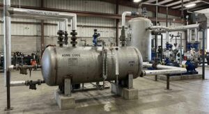
Deaerator tank oxygen removal boiler feedwater ASME fabrication Red River Wyoming

How Do Deaerator Tanks Cut Oxygen in Boiler Systems?

Deaerator tanks cut oxygen by heating boiler feedwater to its saturation temperature and mechanically agitating it so dissolved gases leave solution and vent continuously to the atmosphere, reducing dissolved oxygen to below 0.005 cc per liter. At that level, oxygen pitting corrosion in carbon steel boiler tubes and condensate return lines becomes negligible. Key Takeaways Deaerator oxygen removal works by exploiting the relationship between water temperature and gas solubility. As feedwater temperature rises to saturation, the solubility of dissolved oxygen

Read More »
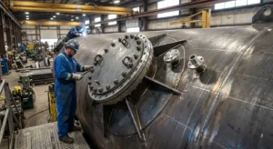
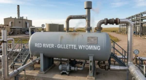
deaerator tank ASME fabrication boiler feedwater steam system Red River Wyoming

Deaerator Tanks: ASME Fabrication for Steam Systems

Deaerator tanks remove dissolved oxygen and other non-condensable gases from boiler feedwater before it enters the boiler, reducing dissolved oxygen content to below 0.005 cc per liter. A feedwater system without effective boiler feedwater deaeration corrodes from the inside, costing facilities far more in tube replacements, chemical treatment, and unplanned shutdowns than the cost of a correctly specified deaerator. Key Takeaways Deaerator tanks physically remove dissolved oxygen and carbon dioxide from boiler feedwater through heat and mechanical agitation, reducing oxygen

Read More »
receiver tank connections fittings nozzle ASME fabrication Red River Wyoming

Which Connections Fit Receiver Tanks?

Receiver tanks typically use NPT threaded connections for smaller ports and flanged or welded connections for larger or higher-pressure applications. The correct connection depends on operating pressure, pipe size, fluid service, and ASME code requirements to ensure safe, reliable performance. Key Takeaways Standard receiver tanks use NPT (National Pipe Taper) threaded connections for ports up to two inches, including air inlet, outlet, drain, pressure gauge, and safety relief valve. Larger connections and high-pressure applications use flanged fittings conforming to ASME

Read More »

How Do Receiver Tanks Affect Cycle Time?

Receiver tanks affect compressor cycle time by extending the off time between starts: more compressed air storage volume means the system draws down pressure more slowly, so the compressor rests longer before restarting. The relationship between receiver volume, pressure differential, and compressor output is governed by the formula t = (V × (P1 − P2)) / (C × Pa), where a larger V directly extends t. Key Takeaways Compressor cycle time is the interval between starts. A receiver tank extends

Read More »

What Size Receiver Tank Is Required for Industrial Use?

The size of the receiver tank required depends on the compressor output in CFM, the allowable time between starts, and the operating pressure band between cut-in and cut-out. The industry-standard sizing formula is V = (C × t × Pa) / (P1 − P2), and every compressed air vessel operating above 15 psig must carry the ASME U Stamp. Key Takeaways The standard sizing formula is V = (C × t × Pa) / (P1 − P2), where V is

Read More »