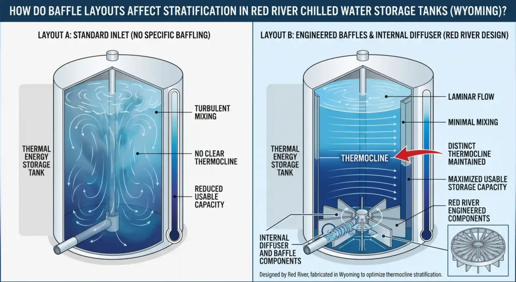
Internal flow distribution controls whether a thermal energy storage tank maintains a sharp thermocline or loses it to turbulent mixing. When baffles and diffusers introduce water at low velocity across the full tank cross-section, stratification efficiency holds at 85 to 95 percent. Without that control, efficiency drops to 60 to 70 percent and the tank must be significantly larger to meet the same storage target.
Key Takeaways
- Baffle layouts affect stratification by controlling whether water enters at low enough velocity and high enough uniformity to maintain a sharp thermocline between cold supply and warm return layers.
- Radial diffusers suit vertical tanks with centerline nozzles. Pipe header and slotted pipe diffusers suit tanks with side-wall nozzles. Each must be sized for the actual operating flow rate range, not just peak flow.
- Horizontal tanks require vertical or inclined internal baffles to compensate for the geometry’s tendency toward thermal mixing. Vertical baffles create staged compartments that maintain temperature separation across the tank length.
- Tank aspect ratio and baffle layout are interdependent. Vertical tanks with 1:1 to 2:1 height-to-diameter ratios give the thermocline sufficient space to stabilize. Tanks below 1:1 aspect ratio limit the effectiveness of any baffle configuration.
- Stratification efficiency ranges from 85 to 95 percent for well-designed tanks to 60 to 70 percent for poorly designed ones. The difference directly affects the tank volume required to meet a given storage target.
What Is the Core Mechanism Behind Thermocline Control?
A thermal energy storage tank stores cooling or heating capacity by maintaining a stable thermal gradient between the cold supply layer at the bottom and the warm return layer at the top. The boundary between these layers, the thermocline, is where stratification either holds or fails.
How Internal Flow Distribution Determines the Outcome
Thermal storage tank baffle design controls how water enters and exits the tank. When cold supply water enters at the bottom, it must be introduced at low velocity and distributed across the full cross-section to avoid creating turbulent jets that mix into the warm return layer above. When warm return water enters at the top, the same principle applies in reverse.
The engineering goal is consistent: introduce flow at low enough velocity and high enough distribution uniformity that the thermocline remains sharp through the full charge and discharge cycle. Red River’s pressure vessel fabrication includes coordinating baffle and diffuser design with vessel geometry during the engineering review so the completed tank achieves the stratification efficiency the volume calculation assumed.
How Does Diffuser Geometry Affect Thermocline Quality?
Diffuser geometry controls the velocity and distribution of water entering the tank, which determines whether the thermocline stays sharp. Radial, pipe header, and slotted diffusers each suit different nozzle locations and flow ranges.
Radial Diffusers
Radial diffusers distribute inlet flow outward from a central point across the tank cross-section. They are common in vertical cylindrical chilled water tanks where the supply and return nozzles are located at the top and bottom centerlines. A well-designed radial diffuser introduces flow at velocities low enough to maintain laminar conditions near the thermocline, preserving the thermal gradient.
The perforation pattern, hole diameter, and plate spacing determine the velocity profile of water entering the tank. The design must balance distribution uniformity against hydraulic resistance across the full operating flow rate range.
Pipe Header Diffusers
Pipe header diffusers use a horizontal pipe with perforations along its length to distribute flow across the tank diameter. They are used in both vertical and horizontal tanks where the nozzle location is on the tank side wall rather than the centerline. Header diffusers are effective when the perforation spacing and hole sizing are matched to the tank diameter and the expected flow velocity range.
For horizontal tanks, pipe header diffusers are often combined with internal baffling to create defined flow paths that compensate for the geometry’s natural tendency toward thermal mixing.
Slotted Pipe Diffusers
Slotted pipe diffusers use continuous slots rather than discrete perforations to distribute flow. The slot geometry provides more uniform velocity distribution along the diffuser length than evenly spaced holes, particularly at lower flow rates where the velocity gradient from inlet to end of a perforated header becomes significant. Slotted diffusers are used where high stratification efficiency is required across a wide operating flow rate range, a key consideration for diffuser design in data center applications with variable cooling loads.
What Baffle Configurations Apply to Horizontal TES Tanks?
Horizontal tanks present a greater stratification challenge than vertical tanks because gravity works perpendicular to the flow direction rather than in alignment with it. Without internal baffling, warm and cold water in a horizontal tank mix readily as buoyancy forces drive cold water downward while warm water rises, regardless of inlet flow direction.
Vertical Baffles
Vertical baffles installed transverse to the tank axis create separate compartments that force flow to travel a defined path from inlet to outlet. Each baffle extends from the tank bottom to a defined height with overflow ports that control flow between compartments. This converts the tank from a single mixed volume into staged zones where temperature gradually transitions from cold supply to warm return.
Inclined Baffles
Inclined baffles at angles to the flow direction align with natural buoyancy stratification, maintaining warm and cold layer separation better than purely horizontal flow paths. They are more complex to fabricate than vertical baffles but deliver superior stratification efficiency in horizontal configurations where the geometry otherwise works against thermal separation.
Red River’s fabrication capabilities include internal baffling and diffuser components fabricated and installed as part of the vessel scope, with dimensional verification of baffle placement against design drawings before the vessel closes.
How Is Stratification Efficiency Measured and What Targets Apply?
Well-designed tanks with properly matched internal flow distribution achieve 85 to 95 percent stratification efficiency. Tanks with poorly designed diffuser and baffle systems achieve 60 to 70 percent, requiring a significantly larger tank to meet the same storage target.
The Calculation and Industry Reference Points
Stratification efficiency follows the same calculation across industrial applications: usable storage delivered divided by nominal tank volume at design delta T. ASHRAE guidelines on thermal storage system design provide reference stratification efficiency targets for chilled water applications. Published research on thermal stratification in large-scale storage systems informs best practice for aspect ratio selection and baffle configuration in industrial TES applications.
How Does Tank Geometry Interact With Internal Flow Distribution Design?
Tank aspect ratio and internal flow distribution are interdependent design variables. A vertical cylindrical tank with a height-to-diameter ratio below 1:1 has too little vertical distance for the thermocline to stabilize. Baffles in this configuration have limited effect because the warm and cold water layers are too close to the inlet and outlet nozzles.
Aspect Ratio Targets
Aspect ratios between 1:1 and 2:1 give the thermocline sufficient vertical distance to maintain stability across a full charge-discharge cycle. The baffle configuration must account for the aspect ratio selected to achieve the target stratification efficiency. ASME Section VIII governs the construction of internal components including baffle plates and diffuser assemblies installed inside coded pressure vessels.
Red River coordinates tank geometry selection with diffuser and baffle configuration during the project engineering phase. See Red River’s modular skid packages for how internal flow distribution design is managed across complete integrated TES skid scopes.
What This Means for Your TES Project
How internal flow distribution affects stratification on a specific project depends on four factors working together: tank orientation, aspect ratio, operating flow rate range, and the delta T achievable with the chilled water system design. No single baffle or diffuser type solves all configurations. The internal flow distribution must be matched to actual operating conditions, not generic standards.
Red River has fabricated thermal storage vessels with engineered internal flow distribution systems for power generation, oil and gas, and biogas clients from Gillette, Wyoming, since 2003. Red River holds active ASME U Stamp and NBBI R Stamp certifications. The same engineering review applied to those projects covers the process tanks, thermal energy storage, and prefabrication scopes Red River carries today.
Work With Red River on Your TES Tank Baffle Layout
Request a quote or call 1-307-257-5332 to discuss your TES tank diffuser and baffle configuration. Red River works through internal flow distribution design with clients before the fabrication scope is defined, so the configuration is matched to actual operating conditions from the start.
Frequently Asked Questions
1. How Do Baffle Layouts Affect Stratification Efficiency in Chilled Water Tanks?
Internal flow distribution controls whether a thermocline holds or degrades during charge and discharge. Well-designed diffusers and baffles introduce flow at low velocity across the full tank cross-section, maintaining a sharp boundary between cold supply and warm return water. Poorly designed systems create high-velocity jets that mix the two layers, dropping stratification efficiency from 85 to 95 percent to 60 to 70 percent.
2. What Is the Difference Between a Radial Diffuser and a Pipe Header Diffuser?
A radial diffuser distributes inlet flow outward from a central point, suited to vertical tanks with centerline nozzles. A pipe header diffuser distributes flow along a horizontal pipe with perforations, suited to tanks with side-wall nozzles. Both aim to introduce flow at low velocity and high distribution uniformity. The choice depends on nozzle location, tank orientation, and the operating flow rate range.
3. Why Do Horizontal Tanks Require More Complex Configurations Than Vertical Tanks?
In a vertical tank, gravity assists stratification by naturally separating cold water at the bottom from warm water at the top. In a horizontal tank, gravity acts perpendicular to the flow direction, so warm and cold water mix readily without internal baffling. Vertical or inclined baffles create defined flow paths that compensate for this geometry and maintain temperature separation between the cold and warm zones.
4. How Does Tank Aspect Ratio Affect Thermocline Stability?
Tanks with height-to-diameter ratios below 1:1 have insufficient vertical distance for the thermocline to stabilize, reducing the effectiveness of any internal flow distribution configuration. Aspect ratios between 1:1 and 2:1 give the thermocline enough vertical space to maintain stability across a full charge-discharge cycle. The diffuser and baffle design must account for the aspect ratio selected to achieve the target stratification efficiency.
5. What Flow Rate Range Should Diffuser and Baffle Design Account For?
The internal flow distribution must maintain acceptable stratification efficiency across the full operating range, from minimum partial-load flow to maximum peak-load flow. Diffuser perforation sizing and baffle orifice configuration that work at peak flow often create poor distribution at minimum flow, and vice versa. The design must be verified across the complete range rather than optimized for a single flow condition.
Related Blog Post
Can Condensate Storage Improve Reliability?
Where Do Condensate Tanks Fit in a Steam System?
Which Nozzles Simplify Maintenance on Pressure Vessels?
How to Vent Condensate Tanks in Steam Systems
What Delta T Drives Volume in Thermal Storage Tanks?
About Author