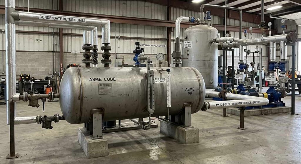
Condensate tanks sit between the condensate return lines and the boiler feedwater pump or deaerator in a steam system, making the condensate tank location a fixed function of the system sequence. The condensate tank collects hot condensate returning from steam traps, holds it at a stable level, and supplies the feedwater pump with a consistent liquid inventory so cavitation does not interrupt the boiler cycle.
Key Takeaways
- Condensate tank location in a steam condensate return system is fixed between the condensate return header and the feedwater pump or deaerator, directly in the boiler feedwater circuit.
- The condensate tank buffers intermittent condensate return flow and provides a stable, continuous liquid supply to the boiler feed pump, protecting the pump from cavitation.
- In systems with a deaerator, condensate flows from the condensate tank to the deaerator before entering the boiler, adding a dissolved oxygen removal step to the condensate tank boiler feedwater sequence.
- In systems without a deaerator, the condensate tank feeds directly to the boiler feed pump, making chemical oxygen treatment more critical.
- Condensate receiver placement must be elevated above the pump centerline to provide the static head needed to suppress vaporization at the pump inlet.
- Red River fabricates ASME-certified condensate tanks designed for direct integration into boiler feedwater systems across oil and gas, power generation, and biogas applications.
What Is the Role of a Condensate Tank in a Steam System?
A steam system generates steam, distributes it to process loads, and collects the condensed liquid that forms when steam releases its heat. That liquid is the condensate, and it is already heated and chemically treated. Recovering it rather than discharging it to drain reduces fuel consumption, makeup water volume, and chemical treatment costs.
Why the Condensate Tank Is a Critical Boiler System Component
The condensate tank collects that returning liquid as one of the core boiler system components in the feedwater circuit. Condensate arrives from steam traps through return lines, enters the tank, and is drawn by the feedwater pump into the next stage of the cycle. The tank provides the buffer volume needed to smooth out variable condensate flow from multiple steam traps across the system.
What Happens Without a Correctly Sized Tank
Without a properly sized and positioned condensate tank, the feedwater pump loses its stable suction source and begins to cavitate, drawing air and flashing vapor instead of liquid water. Condensate tank boiler feedwater supply is what prevents that failure mode from occurring continuously at the pump inlet.
Where Exactly Does the Condensate Tank Sit in the System?
Condensate tank location within a standard industrial steam cycle is downstream of the steam distribution system and upstream of either the deaerator or the boiler feed pump, depending on configuration.
The Steam Condensate Return System Sequence
Steam leaves the boiler, distributes to end-use equipment, and condenses. Steam traps discharge that condensate into return lines that carry it back through the steam condensate return system to the condensate tank. The condensate pump then draws from the tank and pushes liquid forward to the deaerator or directly to the boiler feed pump.
With a Deaerator in the Circuit
In systems with a deaerator, the condensate tank handles collection and buffering while the deaerator handles dissolved gas removal upstream of the boiler. The condensate tank location is upstream of the deaerator inlet in this configuration.
Without a Deaerator
In smaller or lower-pressure systems without a deaerator, the condensate tank feeds the boiler directly through the feed pump. Chemical oxygen scavenging replaces mechanical deaeration in this configuration, making condensate tank boiler feedwater quality monitoring more critical.
Red River fabricates condensate tanks and deaerator storage vessels as ASME-certified pressure vessels to ASME BPVC Section VIII, working through system configuration with clients to confirm vessel sizing, nozzle placement, and connections across the full feedwater circuit. See Red River’s pressure vessel fabrication and thermal energy storage pages for related vessel types used in steam and process systems.
How Does Condensate Receiver Placement Affect Pump Performance?
Condensate receiver placement directly affects condensate pump performance through the net positive suction head available (NPSHA): the pressure energy available at the pump inlet above what is needed to prevent vaporization.
Why Condensate Temperature Creates Cavitation Risk
Condensate operates close to its saturation temperature and vaporizes easily if the pressure at the pump inlet drops too low. When this happens, the pump cavitates: vapor bubbles form at the impeller, collapse violently, and erode the pump internals. Cavitation is one of the most common causes of premature condensate pump failure.
Elevation and Static Head Requirements
The condensate tank must be elevated above the pump centerline to provide the static head needed to suppress vaporization at the pump inlet. Pump manufacturers specify a minimum suction head requirement (NPSHR), and the tank elevation must meet that requirement at minimum liquid level. The tank nozzle location, pump suction nozzle size, and piping arrangement all affect NPSHA and must be coordinated in the fabrication specification.
Red River’s capabilities include condensate tanks with pump suction nozzles positioned to coordinate directly with client-provided condensate pump specifications before fabrication begins.
What Connects to a Condensate Tank?
A condensate tank in a typical industrial boiler system serves as a junction point for multiple piping circuits. Understanding the connection types is essential for correct condensate receiver placement in the system layout.
Condensate Inlet
The condensate inlet receives return flow from the condensate return header. In systems with multiple return lines, a common inlet header on the tank collects flow from all return circuits within the steam condensate return system.
Pump Suction Outlet
The pump suction outlet is the low-point nozzle that feeds the condensate pump. It must be sized and positioned to provide adequate NPSHA at the pump inlet. This is the most critical nozzle from a performance standpoint.
Vent Connection
On atmospheric tanks, the vent connection allows flash steam and dissolved gases to escape to atmosphere or to a flash steam recovery system. On pressurized tanks, the vent is replaced by a pressure relief device and vent header. The vent must be sized to handle the flash steam load generated when hot condensate enters at reduced pressure.
Makeup Water Inlet
The makeup water inlet allows fresh treated water to enter the tank when condensate return is insufficient to maintain the required level for boiler operation. Makeup water is controlled by a float valve or level controller.
Level Instrumentation Nozzles
Level instrumentation nozzles support float-type level gauges or electronic level transmitters used to monitor tank inventory and trigger makeup water, pump start, or high-level alarms.
Red River’s modular skid packages integrate condensate tanks with pumps, level controls, and instrumentation into pre-assembled systems that minimize field connection points and installation time.
How Does Condensate Tank Position Differ Between System Types?
Condensate tank location varies by system scale and operating pressure.
Small Commercial Systems
In small commercial systems, the condensate tank is a single atmospheric vessel at grade feeding one condensate pump, with no deaerator in the circuit. The condensate tank boiler feedwater path goes directly from the tank to the feed pump to the boiler.
Large Industrial Systems
In large industrial systems for power generation or oil and gas, the condensate tank is one of several boiler system components in a defined feedwater sequence, often a pressurized receiver feeding a deaerator before the boiler feed pump. The condensate tank location in these systems is upstream of the deaerator, not directly feeding the boiler.
Biogas and Industrial Process Applications
In biogas and renewable natural gas (RNG) facilities, condensate quality and corrosion control are particularly important because contaminated condensate can affect downstream gas processing equipment. See Red River’s biogas and biomethane page for how condensate vessel requirements are addressed in this sector.
What This Means When Specifying a Condensate Tank
Where do condensate tanks fit in the system is answered by their function: between the condensate return lines and the feedwater circuit, at an elevation coordinated with the pump suction requirement. Condensate tank location, receiver placement elevation, and connection nozzle layout are design decisions made before fabrication, not field adjustments made after the tank is installed.
A tank fabricated without reference to the downstream pump NPSHR or the deaerator inlet elevation creates fit-up problems and performance deficits that cannot be resolved without rework. Getting the condensate receiver placement right at the specification stage is what prevents cavitation failures and startup delays.
Discuss Your Condensate Tank Requirements With Red River
Red River has fabricated ASME-certified condensate tanks for boiler feedwater, steam recovery, and process applications across oil and gas, power generation, biogas, and industrial sectors from Gillette, Wyoming, since 2003. Red River holds active ASME U Stamp and NBBI R Stamp certifications and is an American Welding Society (AWS) member. Every vessel ships with full MTR documentation, hydrostatic test records, and an ASME Authorized Inspector sign-off. Learn more at Red River’s about us page, or request a quote and call 1-307-257-5332 to discuss your condensate system scope.
Frequently Asked Questions
1. Where Does the Condensate Tank Sit Relative to the Boiler?
The condensate tank sits downstream of the steam distribution system and upstream of the deaerator or boiler feed pump, making it a central node in the steam condensate return system. Condensate from steam traps flows back through return lines into the tank, which feeds the feedwater pump that returns liquid to the boiler cycle.
2. Can a Condensate Tank Feed Directly Into a Boiler Without a Deaerator?
Yes, in smaller or lower-pressure systems. When no deaerator is present, the condensate tank feeds directly to the boiler feed pump, and dissolved oxygen is managed through chemical oxygen scavengers added to the feedwater. High-pressure systems and larger industrial boilers typically require a deaerator between the condensate tank and the boiler to meet feedwater oxygen specifications.
3. How High Above the Pump Does a Condensate Tank Need to Be Installed?
The minimum condensate receiver placement elevation depends on the condensate pump’s NPSHR and the condensate temperature. Hot condensate near saturation requires more suction head than cooler liquid. The pump manufacturer specifies the minimum NPSHR, and the system engineer calculates the required tank elevation at minimum liquid level.
4. What Happens If the Condensate Tank Is Undersized?
An undersized tank cannot buffer flow variations between condensate return and pump demand. The level drops below the pump suction nozzle, drawing in air or flash vapor and causing cavitation. Pump cavitation erodes the impeller, reduces flow, and triggers shutdowns. Correct sizing at the design stage prevents this failure mode.
5. Does Red River Fabricate Condensate Tanks as Part of a Skid System?
Yes. Red River fabricates condensate tanks as standalone ASME pressure vessels and as part of integrated modular skid packages that include the condensate pump, level controls, makeup water valve, and instrumentation. Request a quote or call 1-307-257-5332 to discuss your condensate system scope.
Related Blog Post
Can Condensate Storage Improve Reliability?
Which Nozzles Simplify Maintenance on Pressure Vessels?
How to Vent Condensate Tanks in Steam Systems
How Do Baffle Layouts Affect Stratification in TES Tanks?
What Delta T Drives Volume in Thermal Storage Tanks?
About Author