Every time a chiller starts, it draws a large inrush current, creates a pressure shock in the refrigeration circuit, and subjects the compressor to mechanical stress before oil pressure stabilizes. A chiller that cycles on and off every 3–5 minutes experiences more compressor wear in a week than a properly sized system experiences in months. This guide is for mechanical engineers and facility managers who need to understand exactly how buffer tanks prevent chiller short cycling, what causes it, and how to size a buffer tank to eliminate it.
What Is Chiller Short Cycling?
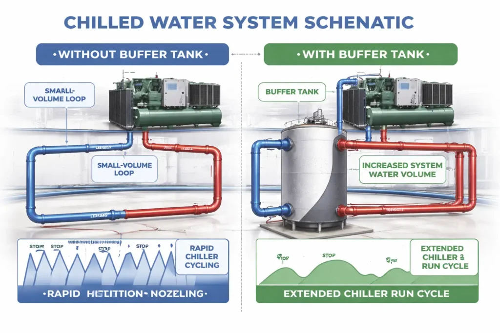
Chiller short cycling occurs when system water volume is too low to absorb minimum cooling output before return temperature hits low-limit cutoff. The chiller starts, produces minimum output, and rapidly cools the small system volume faster than building load absorbs. Return temperature drops to cutoff, chiller shuts off, then restarts within minutes as load continues. This repeats during low-load periods such as mornings, evenings, and mild weather conditions frequently again.
Chiller manufacturers typically specify minimum off-times of 10–20 minutes between starts to allow refrigerant pressures to equalize and oil pressure to stabilize before the next start. Systems that cannot maintain this minimum off-time experience accelerated compressor wear, increased energy consumption per ton of cooling, and shortened equipment life. For ASME fabrication standards governing the pressure vessels used in these systems, the ASME Boiler and Pressure Vessel Code sets the design, material, and inspection requirements that all certified buffer tanks must meet.
The Air-Conditioning, Heating, and Refrigeration Institute (AHRI) publishes chiller performance standards that include minimum cycle time and start frequency requirements.
How Buffer Tanks Prevent Short Cycling
A buffer tank prevents short cycling by increasing total water volume in a chilled water system. More volume adds thermal mass, slowing temperature change in response to chiller output. The time required for system water temperature change is directly proportional to total volume. Doubling volume roughly doubles runtime before return water reaches cutoff, allowing an efficient cycle and meeting minimum off-time requirements. It does not change chiller output, building load, or control setpoints, but simply adds volume and improves mixing and thermal contact.
For more on how chilled water storage tanks and buffer tanks work together in larger systems, Red River’s engineering team can review your system configuration.
The Role of System Water Volume in Cycle Time
The relationship between system water volume and chiller cycle time can be expressed with a straightforward calculation:
Minimum Cycle Time (minutes) = (System Volume in gallons × 8.33 lb/gal × ΔT cutoff in °F) ÷ (Chiller Minimum Output in BTU/hr ÷ 60)
Where ΔT cutoff is the temperature rise needed in the return water to trigger a chiller restart after shutdown.
Example:
- System volume: 500 gallons
- ΔT cutoff: 2°F
- Chiller minimum output: 60 tons = 720,000 BTU/hr
Cycle time = (500 × 8.33 × 2) ÷ (720,000 ÷ 60) Cycle time = 8,330 ÷ 12,000 Cycle time = 0.69 minutes far below the manufacturer’s 10-minute minimum
Adding a 2,000-gallon buffer tank brings total system volume to 2,500 gallons:
Cycle time = (2,500 × 8.33 × 2) ÷ 12,000 Cycle time = 41,650 ÷ 12,000 Cycle time = 3.47 minutes still short but significantly improved
A 5,000-gallon buffer tank brings total volume to 5,500 gallons:
Cycle time = (5,500 × 8.33 × 2) ÷ 12,000 Cycle time = 7.64 minutes approaching the 10-minute minimum
This calculation shows why the rule of thumb of 10 gallons per ton of chiller capacity exists; it approximates the volume needed to achieve adequate cycle times in most standard system configurations. But as the example shows, existing system volume, ΔT cutoff settings, and chiller minimum output all affect the actual buffer volume required. For precise sizing, see our guide on how much volume is needed for chilled water storage.
ASHRAE provides reference guidelines on chilled water system volume and minimum cycle protection in the ASHRAE HVAC Systems and Equipment handbook.
Buffer Tank Placement for Maximum Effectiveness
Where the buffer tank is installed in the piping system directly affects how well it prevents short cycling. Incorrect placement can reduce the tank’s effectiveness even when the volume is correctly sized.
Primary loop placement: The buffer tank should be installed on the primary chiller loop between the chiller and the primary/secondary interface, ensuring full thermal contact with actively conditioned water and maximizing time before return temperature setpoint is reached.
Common pipe or hydraulic separator: In primary/secondary systems, the buffer tank is installed at the common pipe between loops, providing hydraulic decoupling so each loop operates independently at its own flow rate while adding volume to prevent short cycling.
Avoid dead legs: A buffer tank in a dead-end branch with poor circulation adds little to cycle time because water does not fully mix with the active loop. Proper inlet and outlet nozzle placement should drive full-volume circulation, while internal baffles can improve mixing when layout constraints limit optimal positioning.
For modular skid packages that integrate buffer tanks with chillers, pumps, and controls in a pre-engineered assembly, Red River designs the full piping configuration before fabrication begins.
Hydraulic Decoupling The Secondary Function of Buffer Tanks
Beyond short cycling prevention, buffer tanks provide hydraulic decoupling between primary chiller loop and secondary distribution loop in variable-flow systems. Distribution pumps modulate with zone demand; as valves close, secondary flow drops. Without separation, reduced flow reaches chiller, risking minimum flow violations, evaporator freezing, refrigerant migration, and compressor damage. Installed at the interface, the tank absorbs flow differences, maintaining stable chiller flow while allowing secondary modulation freely as required safely.
This decoupling function is particularly important in data center cooling systems where IT load variability causes rapid and large flow changes in the secondary distribution loop. Without hydraulic decoupling, those flow changes propagate directly to the chiller causing both short cycling at low loads and flow starvation during rapid load increases.
Need a Reliable Partner?
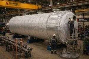
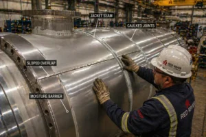
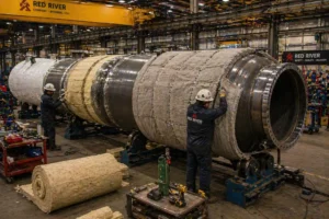
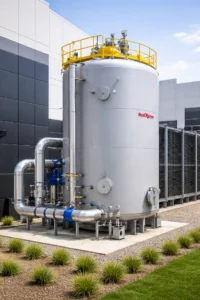
Red River fabricates ASME U-stamp certified buffer tanks sized and configured for each project’s chiller minimum output, system water volume, and minimum cycle time requirements. Every tank includes full material traceability, certified weld documentation, and hydrostatic test records. Contact our team to discuss buffer tank specifications for your chilled water system.
Solving Short Cycling With the Right Buffer Volume
Chiller short cycling is a solvable engineering problem, not an inherent limitation of chilled water systems. The solution is to add sufficient water volume to the primary loop to extend chiller runtime beyond the manufacturer’s minimum off-time at minimum cooling load. Buffer tanks provide this volume in a compact vessel for retrofit or new systems. Properly sized, they eliminate short cycling, reduce compressor wear, lower energy use, extend service life.
Frequently Asked Questions
1. What exactly causes chiller short cycling?
Short cycling occurs when system water volume is too low relative to chiller minimum output, causing rapid cooling that outpaces building load and driving return temperature to low-limit cutoff before minimum off-time is reached.
2. How does a buffer tank extend the chiller’s run time?
By adding water volume to the loop, buffer tank increases system thermal mass, slowing temperature change so the chiller runs longer before return water reaches cutoff setpoint that triggers shutdown cycle efficiency improves overall performance
3. How do buffer tanks prevent chiller short cycling in variable-flow systems?
In variable-flow systems, buffer tanks add volume to extend cycle times and provide hydraulic decoupling between primary chiller and secondary distribution loops, preventing secondary flow reductions from reaching the chiller and causing low-flow damage.
4. What size buffer tank for data centers?
A common starting point is 10 gallons per ton of installed chiller capacity. Data centers with highly variable IT loads or tight supply temperature requirements typically need more volume sizing should be validated against the chiller’s minimum load percentage and the facility’s peak load variability.
5. Which tests verify buffer tank quality?
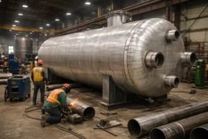
ASME Section VIII Division 1 requires hydrostatic testing at 1.3× MAWP, weld inspection throughout fabrication, and leak testing at operating pressure. An Authorized Inspector must sign off on the Manufacturer’s Data Report (Form U-1) before the U-stamp is applied.
Key Takeaways
- Chiller short cycling occurs when system water volume is too small to absorb the chiller’s minimum output; the loop cools too quickly, triggering the low-limit cutoff before the manufacturer’s minimum off-time has elapsed.
- Buffer tanks prevent short cycling by adding thermal mass to the primary loop doubling the water volume approximately doubles the chiller’s minimum run time at the same load conditions.
- Buffer tank placement on the primary loop with active circulation through the full tank volume is critical; a tank in a dead-end branch contributes little to cycle time regardless of its size.
- Red River fabricates ASME U-stamp certified buffer tanks with full documentation sized against each project’s chiller minimum output, existing system volume, and minimum cycle time requirements before fabrication begins.
Related Blog Post
How Do You Size Thermal Storage for Data Centers?
Thermal Storage Tank Design Engineering