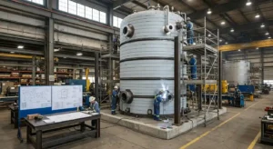
A buffer tank that fails in service does not just require replacement it takes the chilled water system offline, potentially shutting down the cooling infrastructure that protects servers, process equipment, or pharmaceutical storage. The tests performed during fabrication and before commissioning are the only objective verification that the tank will perform reliably under the pressures, temperatures, and thermal cycles it will experience throughout its service life. This guide is for mechanical engineers, facility managers, and procurement teams who need to understand which tests verify buffer tank quality, what each test proves, and what documentation to require before accepting a tank for installation.
Why Buffer Tank Testing Matters
Buffer tanks face pressure, thermal cycling, and hydraulic transients; defects risk fatigue or failure. ASME Section VIII Division 1 governs design, fabrication, and testing for safe chilled water systems.
For a complete overview of ASME code stamped pressure vessels and the certification process, Red River provides full documentation from fabrication through delivery.
Hydrostatic Testing The Primary Pressure Test
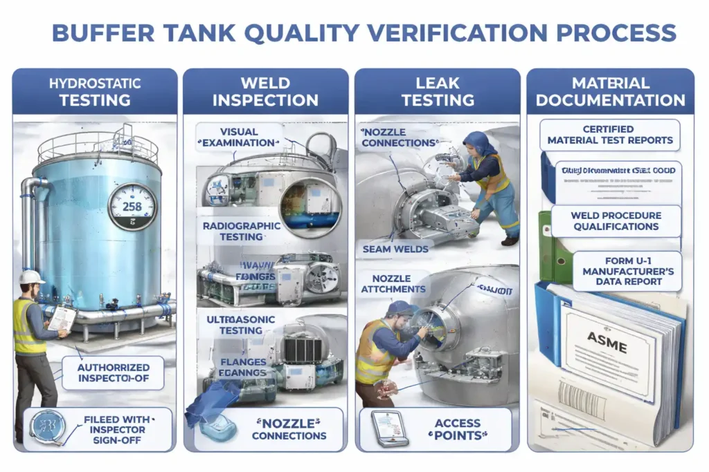
Hydrostatic testing under ASME Section VIII Division 1 confirms integrity after fabrication and before finishing. The tank is water-filled, pressurized to 1.3× MAWP, held 30 minutes, and inspected safely.
The test verifies:
- Shell and head thickness is adequate for design pressure
- All weld seams are free of through-wall defects
- Nozzle attachments and reinforcements are structurally sound
- Pressure relief device connections are correctly positioned and rated
An Authorized Inspector independent of the fabricator witnesses the hydrostatic test and signs off on the result before the U-stamp is applied to the nameplate. This sign-off is recorded on the Manufacturer’s Data Report (Form U-1).
For reference data on pressure vessel testing standards, see the ASME Boiler and Pressure Vessel Code Section VIII Division 1.
Weld Inspection Throughout Fabrication, Not Just at the End
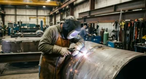
Weld inspection is the most extensive quality verification process in buffer tank fabrication because welds are the most common source of structural failure in pressure vessels. ASME Section VIII specifies weld inspection requirements that apply continuously throughout fabrication not just at the final testing stage.
Visual inspection: is performed on every weld as it is completed. The inspector checks for surface defects including cracks, porosity, undercut, overlap, and incomplete fusion at the weld toe. Visual inspection catches gross defects early in fabrication before they are buried under additional weld passes.
Radiographic testing (RT): Radiographic testing (RT) uses X-ray or gamma-ray imaging to inspect completed welds, detecting subsurface defects such as porosity, slag inclusions, lack of fusion, and cracks. Coverage level determines joint efficiency: 100% RT yields 1.0, 10% RT yields 0.85, and no RT yields 0.70, requiring progressively thicker wall designs.
Ultrasonic testing (UT): uses high-frequency sound waves to detect internal defects and measure wall thickness. UT is used as an alternative to or supplement for RT, particularly at nozzle-to-shell junctions and support attachments where radiographic access is limited.
All weld procedures must be qualified under ASME Section IX the welding and brazing qualifications code before fabrication begins. Welders must hold current certifications for the specific process, material, and position used on each tank. Red River maintains pressure vessel fabrication records for all weld procedures and welder qualifications as part of the quality control system audited by ASME.
Leak Testing Final Verification of Seal Integrity
Leak testing follows hydrostatic testing to confirm all welds, nozzles, flanges, and instrument connections are leak-free at operating pressure. It verifies the assembled tank holds pressure without loss using treated water or glycol at design pressure. Any leaks are repaired and retested before acceptance.
Leak testing is particularly important for tanks with:
- Multiple nozzle connections for supply, return, drain, vent, and instrumentation
- Threaded connections where sealing depends on thread engagement and sealant condition
- Flanged connections where gasket seating load must be verified
- Access manholes or inspection ports where closure integrity must be confirmed
For guidance on inspection standards and registered vessel documentation, the National Board of Boiler and Pressure Vessel Inspectors maintains a registry of certified vessels and authorized inspection agencies.
Material Documentation The Paper Trail That Proves Compliance
Material documentation is not a physical test but it is a mandatory component of ASME certification and one of the most important quality verification items for facilities that must demonstrate infrastructure compliance to clients, insurers, or regulatory authorities.
ASME Section VIII requires that all pressure-containing materials be accompanied by Certified Material Test Reports (CMTRs) that verify:
- Chemical composition matches the specified ASME grade (SA-516 Gr. 70, SA-240 304L, etc.)
- Mechanical properties yield strength, tensile strength, elongation meet the minimum values in ASME Section II Part D
- Heat and lot numbers are traceable from the mill through fabrication to the finished vessel
- Any post-weld heat treatment (PWHT) requirements have been performed and documented
Using non-ASME-approved materials or materials without traceable CMTRs disqualifies the vessel from U-stamp certification. It also creates liability exposure for the specifying engineer and the facility operator if the tank fails in service and materials cannot be verified.
Red River maintains full material traceability for every pressure vessel we fabricate from mill certification through the final Manufacturer’s Data Report ensuring clients have the complete documentation package required for commissioning, insurance, and regulatory review.
The Manufacturer’s Data Report Form U-1
The Manufacturer’s Data Report (Form U-1) is the document that consolidates all test results, material certifications, design calculations, and inspection records into a single certified record for each ASME-stamped vessel. It must be completed and signed by both the manufacturer and the Authorized Inspector before the U-stamp is applied.
Form U-1 documents:
- Vessel identification manufacturer, serial number, year built
- Design conditions MAWP, design temperature, corrosion allowance
- Material specifications ASME grades for shell, heads, nozzles, and supports
- Weld joint efficiencies and NDE performed
- Hydrostatic test pressure and result
- ASME Section and Division under which the vessel was designed and built
- Authorized Inspector name, certification number, and signature
This document is what data center operators, pharmaceutical facilities, and industrial plant managers reference when auditors, insurers, or regulators request proof that installed pressure vessels meet code requirements. Red River provides Form U-1 as standard documentation with every U-stamped buffer tank. Contact our team to discuss documentation requirements for your project.
Need a Reliable Partner?
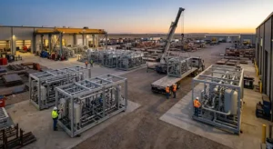
Red River fabricates ASME U-stamp certified buffer tanks with the complete quality verification package hydrostatic test records, weld inspection documentation, CMTRs, and Form U-1 for data centers, industrial facilities, pharmaceutical plants, and large commercial cooling systems. Contact our team to discuss buffer tank fabrication and certification for your chilled water system.
Accepting a Buffer Tank What to Verify Before Installation
Before accepting a buffer tank, verify Form U-1 signed by manufacturer and Authorized Inspector, CMTRs for materials, hydrostatic test records at 1.3× MAWP, weld inspection/NDE reports, and welder qualifications. Without this documentation, ASME compliance cannot be confirmed, and the vessel should not be installed in a pressurized system.
Frequently Asked Questions
1. What is the primary test that verifies buffer tank structural integrity?
Hydrostatic testing at 1.3× MAWP verifies ASME Section VIII Division 1 integrity. The tank is water-filled, pressurized, held 30 minutes, and inspected for leaks or deformation before U-stamp approval.
2. Why is weld inspection performed throughout fabrication rather than just at the end?
Early weld pass defects can be hidden by subsequent layers, making them undetectable at final inspection. Continuous inspection identifies issues early, enabling repair without rework and ensuring consistent weld quality.
3. What is the difference between full and spot radiography for buffer tank welds?
Full radiography (100% RT) inspects all seam welds for 1.0 joint efficiency, enabling full allowable stress use. Spot RT (10%) yields 0.85 efficiency, requiring thicker walls and affecting final design.
4. How do buffer tanks prevent chiller short cycling?
Buffer tanks increase total system water volume, slowing the rate of temperature change in the loop. This gives the chiller time to complete a full run cycle before return water temperature drops to the cutoff setpoint preventing the rapid start-stop cycles that wear out compressors and reduce system efficiency.
5. What size buffer tank for data centers?
A common starting point is 10 gallons per ton of installed chiller capacity. Data centers with highly variable IT loads or tight supply temperature requirements may need more volume. Sizing should be validated against the chiller’s minimum load percentage and the facility’s peak load variability before specifying.
Key Takeaways
- Hydrostatic testing at 1.3× MAWP fills the tank with water, holds pressure 30 minutes, and is inspected by an Authorized Inspector before U-stamp approval.
- Weld inspection occurs throughout fabrication using visual checks after each pass and radiographic or ultrasonic testing, since early defects cannot be detected at final inspection.
- Form U-1 is the ASME compliance document signed by manufacturer and Authorized Inspector, required for data center commissioning, insurance approval, and regulatory review.
- A buffer tank without Form U-1, CMTRs, and hydrostatic test records cannot be verified ASME-compliant and should not be installed in pressurized systems.
Related Blog Post
Where Should Industrial Tanks Be Located?
How Do Tie-Ins Impact Downtime
What Are Thermal Storage Tank Design Parameters?
Can Modularization Speed Builds on Industrial Projects?