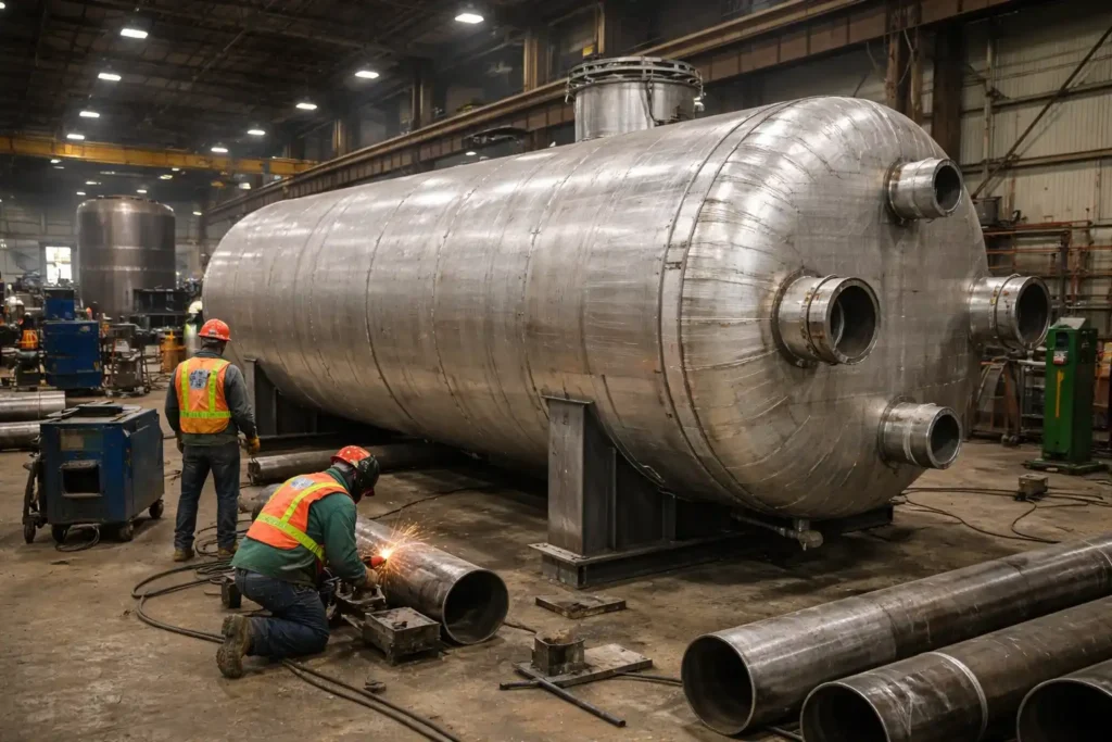
Thermal storage tank design engineering determines whether a tank survives its operating environment or fails under conditions it was never properly specified for. This guide is for engineers, procurement managers, and project leads specifying thermal storage vessels for oil and gas, power generation, or bio gas applications.
Why Thermal Storage Tank Design Engineering Is a Distinct Challenge
Not every pressure vessel or storage tank faces the same design demands. A tank holding ambient-temperature water at low pressure is a fundamentally different engineering problem. A vessel cycling between 50 and 650 degrees Fahrenheit under sustained pressure demands a different level of design discipline.
Thermal storage tanks introduce variables that standard vessel design often underestimates. Shell, nozzle, and support structure expansion must all be accounted for in the mechanical design. Differential expansion between dissimilar materials generates stress concentrations that fatigue welds over time.
Thermal fatigue is one of the most common root causes of in-service pressure vessel failures. A tank without adequate cyclic thermal loading analysis will develop cracks at nozzle welds, support attachments, or shell-to-head junctions. These failures arrive long before the vessel reaches its nominal service life. Red River engineers thermal storage and pressure vessel solutions with these failure modes in mind from the first design review.
ASME Code Requirements for Thermal Storage Tanks
The governing code for most thermal storage vessels is ASME Section VIII. Division 1 covers standard applications. Division 2 applies to higher-pressure or fatigue-sensitive designs and introduces explicit fatigue analysis requirements for vessels subject to significant thermal cycling. ASME Section I applies to power boilers and steam drums in power generation applications.
ASME material specifications cover elevated-temperature allowable stresses, not just ambient-temperature mechanical properties. Carbon steel loses stress capacity as temperature rises. Above defined limits, alloy steels or austenitic stainless steels are required.
Red River holds an active ASME U Stamp certification covering pressure vessel fabrication under Section VIII. Every tank is built, inspected, and documented under that certification. A third-party authorized inspector is on-site for all required hold points. Verify active certifications at asme.org.
Material Selection in Thermal Storage Tank Design Engineering
Material selection is the most consequential decision in thermal storage tank design engineering. The wrong material does not just underperform. It creates a vessel that degrades in service in ways that are often not visible until a failure occurs.
Thermal storage tank design engineering: Carbon steel (SA-516 Grade 70)
SA-516 Grade 70 is the workhorse material for pressure vessels in moderate temperature service. It offers good toughness, weldability, and availability at competitive cost. Its upper temperature limit for ASME pressure vessel service is approximately 800 degrees Fahrenheit. Allowable stress values begin declining meaningfully above 650 degrees Fahrenheit. For thermal storage applications in oil and gas and power generation below these thresholds, SA-516-70 is typically the right starting point.
Chrome-moly alloy steels (P11, P22, P91)
For applications above the carbon steel temperature ceiling, chrome-moly steels are the standard solution. These alloys maintain higher allowable stresses at elevated temperatures and offer better resistance to hydrogen attack and creep at sustained high temperatures. P91 (9Cr-1Mo-V) is widely used in high-temperature power generation applications where long-term creep resistance is a design requirement.
Austenitic stainless steel (304, 316, 321)
Austenitic stainless steels are used in thermal storage applications where corrosion resistance, cryogenic service, or very high temperatures are involved. Their higher coefficient of thermal expansion compared to carbon steel requires careful attention to differential expansion in mixed-material assemblies. Grade 321 includes titanium stabilization to resist sensitization during thermal cycling. It is preferable over 304 in applications with sustained exposure in the 800 to 1,500 degree Fahrenheit range.
Clad and lined vessels
In applications where corrosion resistance is required but full stainless construction is cost-prohibitive, cladding or internal lining is a practical solution. A carbon steel or chrome-moly shell with stainless or nickel alloy cladding provides the structural performance of the base metal. The liner delivers corrosion resistance at significantly lower material cost than full stainless construction.
Red River’s prefabrication team works through material selection as part of the early design review, not as an afterthought once fabrication is underway.
Thermal Insulation Design and Its Impact on Vessel Engineering
Insulation is not a separate scope item that gets added after the vessel is designed. The insulation system affects the vessel’s operating temperature profile, the external surface temperature during operation, and the support structure design. All three have engineering implications.
A well-insulated vessel maintains a more uniform temperature across the shell wall. Poor insulation creates temperature gradients that drive differential thermal expansion across the vessel cross-section, generating bending stresses in the shell. Personnel protection requirements under OSHA limit accessible external surface temperatures to 140 degrees Fahrenheit or lower, and insulation thickness must be calculated to meet this limit during design. Insulated vessels also require insulated support systems to prevent thermal bridging at saddle or leg attachments.
Nozzle Design and Thermal Stress Management
Nozzles are the highest-stress locations on most pressure vessels. In thermal storage tanks, they carry an additional burden. Each nozzle is the connection point between the vessel shell and the attached piping, and both expand and contract with temperature changes independently.
Nozzle design for thermal service requires coordination between the vessel engineer and the piping engineer. The piping flexibility analysis must account for the nozzle loads imposed by thermal expansion of both the pipe and the vessel. If the piping system is too stiff, it imposes loads on the nozzle that the vessel was not designed to carry. These loads are not visible in a standard hydrostatic test. They may not produce immediate failure, but they accumulate fatigue damage at the nozzle weld with every thermal cycle.
Reinforcement pad design, nozzle-to-shell weld geometry, and wall-to-nozzle neck transitions all affect the stress concentration factor at this joint. For fatigue-sensitive applications, finite element analysis of the nozzle junction may be warranted. Red River coordinates nozzle design with client piping engineers as standard practice for thermal service vessels.
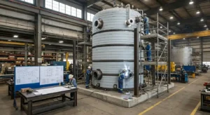
Fabrication Considerations in Thermal Storage Tank Design Engineering
Thermal storage tank design engineering continues through fabrication, introducing requirements that standard ambient-temperature vessel work does not always address.
Preheat and post-weld heat treatment (PWHT)
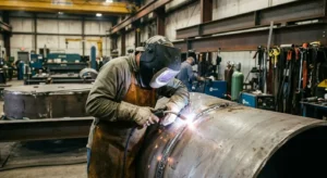
Chrome-moly alloy steels require controlled preheat before welding and post-weld heat treatment (PWHT) to relieve residual stresses and restore heat-affected zone properties. Red River performs PWHT in-house for vessels within furnace capacity. Larger vessels are handled using field-applied resistance heating under controlled procedures.
Dimensional control during fabrication
Thermal service vessels are often fabricated to tighter dimensional tolerances than standard vessels because the thermal expansion calculations assume specific geometry. Out-of-round shells, skewed nozzles, or mislocated support attachments all affect how the completed vessel expands in service.
For multi-nozzle vessels, thermal expansion must be coordinated across multiple connection points. Dimensional verification of nozzle locations during fabrication is a required inspection step, not a final check. Red River verifies critical dimensions at defined fabrication stages, not only at completion. Corrections can then be made while the vessel is still accessible.
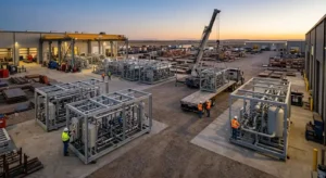
Red River’s modular skid capability means thermal storage vessels can be delivered pre-connected to associated piping, insulation support structures, and instrumentation. This reduces field thermal stress risks from connecting a newly fabricated vessel to existing piping not designed to the same flexibility standards.
Thermal Storage Tank Design Engineering in Oil and Gas, Power Generation, and Bio Gas
Each sector that uses thermal storage tanks has distinct design drivers that affect how these engineering principles get applied.
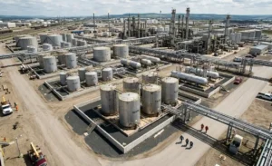
Oil and gas
Thermal storage in oil and gas covers heated separator vessels, fuel gas conditioning systems, and process vessels handling heavy crude or wax-containing fluids above their pour point. The design driver is typically moderate temperature (200 to 450 degrees Fahrenheit) combined with process pressure and reliable operation in remote locations.
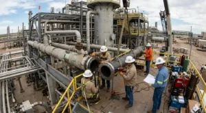
Power generation
Power generation thermal storage includes feedwater heaters, steam accumulators, condensate receivers, and high-temperature thermal energy storage vessels. These applications frequently push beyond carbon steel limits and require chrome-moly or stainless materials. Red River’s capabilities cover the full fabrication scope.
Bio gas
Biogas upgrading and combined heat and power (CHP) systems use thermal storage to buffer heat recovery from engine or turbine exhaust. The temperature range is typically moderate (180 to 350 degrees Fahrenheit). The corrosive nature of biogas condensate and the continuous cycling duty of CHP systems make material selection and fatigue management critical design considerations.
Vessels in biogas service may require stainless steel or coated carbon steel to resist condensate corrosion. CHP applications with frequent start-stop cycling accumulate fatigue cycles faster than baseload systems. This affects the design margin and inspection frequency required over the vessel service life.
Ready to Engineer and Build Your Thermal Storage Tank to Code?
Every thermal storage tank Red River fabricates starts with a thorough design review of your operating conditions, applicable code, and material requirements. If you are specifying a thermal storage tank design engineering scope, Red River works through the full project from design coordination to vessel delivery. That includes ASME code compliance, material selection, fabrication, and complete documentation.
Request a quote or call 1-307-257-5332 to discuss your thermal storage vessel scope with Red River’s fabrication team.
Frequently Asked Questions
1. What is the difference between a thermal storage tank and a standard pressure vessel?
A standard pressure vessel is designed primarily around operating pressure and ambient or near-ambient temperature. A thermal storage tank is a pressure vessel with an additional design load: significant, often cyclic, thermal input. This adds fatigue analysis, elevated-temperature material allowables, thermal expansion management, and insulation system engineering to the design scope.
2. How does ASME Section VIII Division 2 differ from Division 1 for thermal vessels?
Division 2 allows higher allowable stresses than Division 1, which can reduce wall thickness and vessel weight. In exchange, it requires more rigorous design analysis, including formal fatigue assessments for vessels subject to cyclic loading. For thermal storage tanks that cycle frequently, Division 2 is often the more appropriate design basis even if Division 1 would technically permit the vessel.
3. What causes thermal fatigue cracking in storage tanks?
Thermal fatigue cracking develops at stress concentration points. Nozzle welds, support attachments, and shell-to-head junctions. Cyclic thermal expansion and contraction generate repeated stress cycles at these locations. Each cycle causes a small increment of fatigue damage. Over thousands of cycles the accumulated damage initiates a crack.
4. Does Red River perform post-weld heat treatment in-house?
Yes. Red River performs PWHT in-house for vessels within furnace capacity. For larger vessels or field applications, resistance heating is applied under controlled, documented procedures that meet ASME requirements. PWHT records are included in the vessel documentation package delivered to the client.
5. How does thermal storage tank design connect to modular skid fabrication?
Delivering a thermal storage vessel as part of a complete modular skid resolves piping flexibility analysis, insulation support design, and nozzle load coordination in the shop. Field installation then means connecting the skid, not assembling individual components on-site.
Key Takeaways
- Thermal storage tank design engineering must account for thermal fatigue, differential expansion, and cyclic loading from the first design review. These are not issues that can be corrected after fabrication.
- ASME Section VIII Division 1 or Division 2 governs most industrial thermal storage vessels. Division 2 introduces formal fatigue analysis requirements for cyclically loaded vessels that Division 1 does not require.
- Material selection is driven by operating temperature, corrosion environment, and cyclic duty. Carbon steel (SA-516-70) covers moderate temperature service. Chrome-moly and stainless alloys are required above its temperature ceiling.
- Nozzle design for thermal service requires coordination with the piping flexibility analysis. Nozzle loads from thermal expansion of connected piping are a leading cause of in-service fatigue cracking.
- Post-weld heat treatment (PWHT) is required for chrome-moly alloy vessels and must be controlled precisely. Shops without in-house PWHT capability introduce quality risk.
Related Blog Post
Where Should Industrial Tanks Be Located?
How Do Tie-Ins Impact Downtime
What Are Thermal Storage Tank Design Parameters?
Can Modularization Speed Builds on Industrial Projects?
Which Weld Procedures Are Common in Vessel Fabrication
About Author