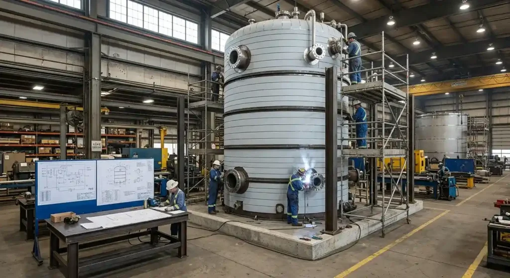
Thermal storage tank design parameters define the full operating envelope of a TES vessel: operating pressure and code basis, temperature range and cyclic loading profile, storage volume, material specification, insulation system requirements, and nozzle configuration. All parameters must be confirmed before fabrication scope is defined, because a vessel that cycles daily accumulates fatigue loads, stratification demands, and thermal expansion forces that standard vessel specifications do not address.
Key Takeaways
- TES design parameters extend beyond standard vessel inputs to include cyclic thermal loading, stratification requirements, insulation system integration, and nozzle-to-piping thermal expansion coordination.
- Operating pressure determines code applicability. Above 15 psig requires ASME Section VIII and U Stamp fabrication; below that threshold follows AWWA D100 or applicable construction standards confirmed during design review.
- Daily charge-discharge cycling accumulates thermal fatigue faster than steady-state service. Nozzle reinforcement, support attachment design, and weld transitions must be designed for cyclic loading from the start.
- Tank geometry affects stratification performance. Vertical tanks with 1:1 to 2:1 aspect ratios maintain the strongest thermocline and deliver 85 to 95 percent usable storage capacity when diffuser design is coordinated with geometry.
- Insulation system parameters must be defined during fabrication, not after delivery. Support ring spacing, jacketing provisions, and vapor barrier design are incorporated into the vessel during shop fabrication.
- All design parameters must be confirmed before fabrication scope is finalized. Correcting design parameter errors after fabrication is complete costs significantly more than resolving them at the start.
Why Do Thermal Storage Tank Design Parameters Require More Than Standard Vessel Inputs?
These design parameters require more than standard vessel inputs because a TES vessel cycles daily, stratifies, and expands against attached piping in ways a steady-state vessel does not. Standard pressure vessel design starts with operating pressure and temperature, material selection, and a code reference. TES tank design requirements extend that foundation to include cyclic thermal loading, stratification performance, insulation system integration, and the interaction between vessel expansion and attached piping.
How Daily Cycling Changes the Design Requirement
A tank cycling between 40 and 180 degrees Fahrenheit daily accumulates thermal fatigue cycles a steady-state vessel never sees. A chilled water storage tank requires diffuser geometry coordinated with vessel design to maintain thermocline stratification, and a hot water storage vessel requires insulation provisions sized during fabrication rather than added after delivery.
How Red River Approaches the Design Parameter Review
Red River’s pressure vessel fabrication covers the full range of ASME thermal storage vessel parameters from initial design review through final documentation delivery. Every project starts with a parameter review before fabrication scope is defined.
What Operating Pressure and Code Requirements Apply to TES Vessels?
Operating pressure is the first TES design input, because it sets the code basis for everything that follows. The applicable standard determines fabrication certification requirements, inspection program, and documentation scope.
How Pressure Class Sets the Code Basis
Vessels operating above 15 psig require fabrication under ASME Section VIII by a U Stamp-certified fabricator, with third-party authorized inspection and a complete ASME Form U-1 documentation package. Atmospheric tanks operating below 15 psig are confirmed to the applicable construction standard during design review. Operating pressure governs code selection before any other design input is evaluated.
When Does Division 2 Apply to TES Vessels?
Within ASME Section VIII, Division 1 covers the majority of TES vessels in standard industrial service. Division 2 applies to higher-pressure or fatigue-sensitive designs where detailed stress analysis and explicit fatigue evaluation are required. TES vessels with daily charge-discharge cycling may warrant Division 2 analysis when cycling frequency and temperature differential combine to produce meaningful fatigue loading at nozzle welds and support attachments. Red River works through this selection with clients before fabrication begins so the correct code basis is established from the start.
How Does Operating Temperature Range Affect TES Tank Design Criteria?
The operating temperature range drives both material selection and the cyclic loading the vessel must sustain. A modest chilled water range and a high-temperature process range place very different demands on the design.
Temperature Range and Material Allowable Stress
Chilled water tank design criteria for a vessel cycling between 38 and 60 degrees Fahrenheit are very different from a hot water storage vessel cycling between 120 and 400 degrees Fahrenheit. Carbon steel maintains adequate allowable stress values under ASME Section VIII up to approximately 800 degrees Fahrenheit, but values begin declining meaningfully above 650 degrees Fahrenheit, pushing the design toward heavier wall thickness or alloy steel alternatives. A high-temperature process heat storage vessel above 600 degrees Fahrenheit requires chrome-moly alloy steel to maintain code-compliant allowable stress values.
How Cyclic Loading Affects Nozzle and Weld Design
Daily charge-discharge cycling accumulates thermal fatigue cycles faster than vessels in steady-state or intermittent service. Nozzle reinforcement design, support attachment geometry, and transition details at shell-to-head junctions must account for repeated stress cycling, not just static design loads. Stress concentration factors at weld toes and geometric discontinuities drive fatigue life calculations. Red River’s fabrication capabilities include working through fatigue considerations during the design review phase for TES vessels with demanding cycle requirements.
What Material Selection Parameters Apply to Industrial Thermal Storage Design?
Material selection for industrial thermal storage design follows operating temperature, water chemistry, chloride exposure, and design service life. Carbon steel covers standard service; stainless and chrome-moly alloys address aggressive or high-temperature applications.
When Carbon Steel Is the Right Material Choice
Carbon steel plate to ASTM A516 Grade 70 is the standard material for TES vessels operating within normal temperature and water chemistry conditions. For chilled water service, a two-part epoxy interior coating protects the carbon steel in closed-loop water chemistry systems. Material selection follows the same criteria regardless of end use: water chemistry compatibility, chloride exposure, design service life, and operating temperature range. See Red River’s process tanks and storage vessel fabrication scope for related material applications.
When Stainless Steel or Alloy Materials Are Required
Stainless steel grades, primarily Type 304 and 316L, are specified for TES vessels with aggressive water chemistry, elevated chloride exposure, or design service life requirements above 30 years. Chrome-moly alloy steels including P11, P22, and P91 cover high-temperature TES applications in power generation and process heating where carbon steel allowable stress values are insufficient. Clad or lined vessel construction combines a carbon steel or alloy shell with a stainless or nickel alloy interior surface, reducing material cost compared to full stainless construction while maintaining chemical compatibility.
How Are Storage Volume and Tank Geometry Parameters Determined?
Storage volume is derived from peak load, discharge duration, temperature differential, and stratification efficiency. Tank geometry, defined by aspect ratio, then determines how much of the nominal volume is actually usable.
How Volume Is Calculated From Thermal Load Requirements
Storage volume is a derived design parameter calculated from peak load, required discharge duration, temperature differential between charge and discharge states, and stratification efficiency. For chilled water applications, the volume calculation starts with peak cooling load, multiplies by discharge duration, and divides by the product of delta T and stratification efficiency.
How Aspect Ratio Affects Thermocline and Usable Capacity
Tank geometry directly affects stratification performance. Vertical tanks with aspect ratios between 1:1 and 2:1 (diameter to height) maintain the strongest thermocline. Tanks that are too squat mix the warm and cold water layers, reducing usable capacity to 60 to 70 percent of nominal volume. Tanks that are too tall introduce pumping head and maintenance complications. The aspect ratio selection is coordinated with diffuser design during the design parameter review, since both geometry and diffuser configuration determine how much of the nominal volume delivers usable storage capacity.
What Insulation System Parameters Must Be Defined During Fabrication?
Insulation system parameters for TES tanks must be defined during fabrication, not after delivery. The insulation thickness calculation drives support ring spacing, jacketing attachment provisions, and access opening locations that are incorporated into the vessel during shop fabrication.
Why Vapor Barrier Design Is the Critical Insulation Variable
For chilled water vessels, vapor barrier continuity is the critical insulation system requirement. Any breach allows moisture to migrate into the insulation layer, degrading thermal performance and accelerating corrosion under insulation (CUI) over time. ASHRAE thermal performance standards and personnel protection requirements under OSHA drive minimum insulation thickness and vapor barrier specifications for occupied mechanical rooms and outdoor installations. Red River’s thermal energy storage services coordinate insulation system parameters during vessel design review so the fabricated vessel is ready for insulation application without field rework.
What Nozzle and Connection Parameters Must Be Confirmed Before Fabrication?
Nozzle locations, orientations, sizes, and pressure ratings are TES tank design requirements that need coordination between the vessel engineer and the piping and instrumentation designer before fabrication begins.
How Thermal Expansion Loads Affect Nozzle Design
Nozzle loads from thermal expansion of attached piping must be calculated and verified against the vessel nozzle design before fabrication begins. Daily cycling repeats those loads with every charge-discharge cycle, making fatigue at nozzle welds a design consideration from the start.
How Supply and Return Nozzle Location Drives Diffuser Design
Supply and return nozzle locations for chilled water TES tanks determine how the diffuser system distributes flow inside the vessel. Diffuser placement and perforation sizing are set during the design review alongside the nozzle location parameters. Getting nozzle and diffuser parameters right before fabrication begins avoids costly field modifications to connection points after delivery. See Red River’s modular skid packages for how nozzle and connection parameters are managed across complete integrated TES skid scopes.
Thermal Storage Tank Design Parameters Red River Confirms Before Fabrication
Red River works through thermal storage tank design parameters before fabrication scope is defined on every TES project. Red River holds active ASME U Stamp and NBBI R Stamp certifications and has fabricated TES vessels for power generation, oil and gas, and biogas clients from Gillette, Wyoming, since 2003. The National Board maintains registration records for all ASME-stamped vessels Red River delivers. See Red River’s prefabrication services for how parameter reviews carry through to complete modular TES skid scopes.
Ready to Confirm Your TES Vessel Design Parameters?
Request a quote or call 1-307-257-5332 to discuss your thermal storage tank design parameters and fabrication scope with Red River’s team. The earlier the parameter review starts, the more options remain available for material selection, geometry, and schedule.
Frequently Asked Questions
1. What Are the Primary Thermal Storage Tank Design Parameters for an ASME-Coded Vessel?
The primary parameters are operating pressure and code basis, operating temperature range and cyclic loading profile, storage volume based on load and discharge duration, material specification, insulation system requirements, and nozzle locations, sizes, and ratings.
2. How Does Cyclic Thermal Loading Affect Thermal Storage Tank Design?
Daily charge-discharge cycling accumulates thermal fatigue cycles faster than steady-state service. Nozzle reinforcement design, support attachment geometry, and weld transition details must all account for repeated stress cycling from the start of the design process.
3. When Does ASME Section VIII Division 2 Apply to TES Vessels?
The Division 1 versus Division 2 choice is driven by pressure level, required design life, and cyclic loading severity rather than temperature range alone. Division 2 applies when detailed fatigue analysis is required, typically for vessels with significant daily cycling at elevated temperature differentials or when the owner’s specification requires explicit fatigue evaluation.
4. How Is Insulation Thickness Determined for a Thermal Storage Tank?
Insulation thickness is calculated to meet personnel protection surface temperature limits and thermal performance requirements. For chilled water vessels, vapor barrier design is the critical variable. These calculations must be completed during fabrication so support ring spacing, jacketing provisions, and access openings are incorporated before the vessel leaves the shop.
5. What Nozzle Parameters Need to Be Confirmed Before Fabrication Begins?
Nozzle size, pressure rating (flange class), location on the vessel shell, orientation, reinforcement design, and the piping nozzle loads from thermal expansion of the attached piping system all need to be confirmed before fabrication. For chilled water TES vessels, supply and return nozzle locations also drive diffuser placement and perforation sizing.
6. What Documentation Is Required for Thermal Storage Tank Design Parameters?
The vessel design is documented in the ASME Form U-1 manufacturer’s data report, which records design pressure, design temperature, material specifications, weld examination requirements, and hydrostatic test results. Supporting documents include certified mill test reports, weld procedure specifications, and NDE reports. The National Board maintains registration records for all ASME-stamped vessels. For modular skid scopes, as-built drawings and an operations and maintenance manual are also included.
Related Blog Post
Condensate Tanks: Types, Fabrication, and ASME Code
Which Tests Validate Deaeration in Pressure Systems?
Equalization Tanks: Design, Sizing, and Fabrication
What Are Thermal Storage Testing Standards for TES Vessels?
What Hydro Tests Are Required for Pressure Vessels?
- Equalization Tanks: Design, Sizing, and Fabrication
- What Are Thermal Storage Testing Standards for TES Vessels?
- What Hydro Tests Are Required for Pressure Vessels?
- What Is Thermal Energy Storage System Manufacturing?
- Thermal Storage Tanks for Industrial Use
- Thermal Energy Storage Solutions for Industrial Applications
About Author