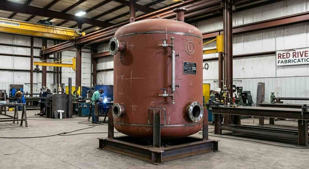
Make-up water tanks replenish fluid lost from closed industrial loops through evaporation, leakage, blowdown, or maintenance drains, maintaining system volume and pressure without interrupting operation. The vessel holds a reserve of treated water or process fluid and releases it into the loop automatically when system pressure or level falls below a set point.
Key Takeaways
- Make-up water tanks are designed to replenish fluid losses in closed hydronic, cooling, steam, and process loops, maintaining system volume so the circulating pump always has fluid at the suction inlet.
- Makeup water tank sizing is based on the expected daily fluid loss rate, the interval between manual refills or automatic makeup water deliveries, and the system’s minimum acceptable reserve volume.
- Make-up water vessel design must confirm material compatibility with the treated water chemistry, operating temperature, and any chemical additives in the loop before fabrication begins.
- HVAC make-up water tanks in pressurized closed-loop heating and cooling systems must carry the ASME U Stamp under Section VIII, Division 1, when operating above 15 psig.
- Process makeup water tanks in industrial systems face more demanding chemistry requirements than HVAC applications, including corrosion inhibitor compatibility, pH range, and in some cases potable water contact standards.
- Red River fabricates ASME-certified make-up water tanks in carbon steel and stainless steel for hydronic, process cooling, steam, and biogas applications from Gillette, Wyoming, since 2003.
What Is a Make-Up Water Tank?
A make-up water tank is a storage vessel that holds treated water or process fluid in reserve to replenish losses from a closed loop. Closed industrial loops, whether hydronic heating systems, chilled water cooling circuits, steam condensate systems, or process cooling loops, lose fluid continuously through evaporation, blowdown, leakage, maintenance drains, and flash steam loss from condensate systems.
Why Fluid Loss Matters for Loop Integrity
When a closed loop loses more fluid than it receives, system pressure drops, the pump begins to cavitate, and eventually the loop cannot circulate fluid. A make-up water tank prevents that failure by holding treated water in reserve and releasing it automatically when the system needs replenishment. The tank is a passive protection system for the circulating pump and for the chemical treatment program that depends on maintaining the correct fluid volume and concentration.
Sources of Fluid Loss in Closed Loops
Evaporation from open cooling towers removes water continuously from open circuits. Boiler and cooling tower blowdown intentionally removes concentrated water to control dissolved solids and must be replaced with fresh treated water. Leakage at shaft seals, flange joints, and valve packing accumulates over days and weeks. Maintenance drains remove larger volumes intermittently. Flash steam from condensate systems and steam traps releases water vapor that does not return to the condensate circuit.
Where Are Make-Up Water Tanks Used?
Make-up water tanks appear in any system where fluid loss must be replenished to maintain continuous operation.
Hydronic Heating and Cooling Systems
Closed hydronic loops in commercial and industrial facilities lose fluid at low rates through shaft seals, air vents, and maintenance events. An HVAC make-up water tank connected to the loop through a pressure-reducing valve or a float-controlled valve replenishes these losses automatically and keeps the system at design pressure. See Red River’s thermal energy storage fabrication scope for how make-up water vessels are integrated with hydronic TES systems.
Industrial Process Cooling
Process cooling loops in manufacturing, chemical processing, and pharmaceutical production use make-up water tanks to replenish losses from heat exchangers, cooling jackets, and spray systems. The make-up water must be compatible with the loop’s chemical treatment and with the materials of the heat transfer equipment it contacts. Contaminated or incompatible makeup water degrades the inhibitor package and causes accelerated corrosion throughout the loop.
Boiler and Steam Systems
Boiler feedwater systems use make-up water to replace condensate that does not return to the boiler feed circuit. Make-up water added to a boiler system requires treatment before it enters the deaerator or feed pump to remove hardness, dissolved oxygen, and silica that would cause scaling and corrosion inside the boiler. See Red River’s process tanks page for how make-up water vessels are configured for steam system applications.
Biogas and Anaerobic Digestion
Biogas digester systems use water to maintain digester liquid volume and dilute incoming feedstock. Make-up water tanks in biogas applications must be compatible with the biological process chemistry and must not introduce contaminants that would inhibit microbial activity or affect biogas quality.
How Is a Make-Up Water Tank Sized?
Makeup water tank sizing starts with quantifying the total expected fluid loss rate and the interval over which the tank must supply makeup fluid without being refilled.
Key Sizing Inputs
The key inputs for make-up water vessel design sizing are: daily fluid loss rate from all identified sources (evaporation, blowdown, leakage, maintenance), maximum acceptable interval between refills or automatic delivery, system minimum pressure and minimum acceptable loop volume, required reserve volume to handle unexpected loss events above the normal rate, and chemical treatment batch volume if the tank also introduces treatment chemicals to the loop.
Sizing Method With Worked Example
The minimum tank volume equals the daily fluid loss rate multiplied by the required autonomy period in days, plus the reserve margin. A system losing 200 gallons per day that must operate for five days without refill requires a minimum of 1,000 gallons of usable storage. A reserve margin of 20 to 25 percent is standard practice, bringing the specified volume to 1,200 to 1,250 gallons.
Accounting for Chemical Feed
Many make-up water tanks also serve as the point of introduction for corrosion inhibitors, biocides, or pH adjustment chemicals. When the tank is used for chemical feed, the sizing must account for the batch volume needed to treat the loop and the concentration at which the chemical must be introduced to achieve the target loop concentration. Red River’s capabilities cover make-up water tank configurations that integrate chemical feed connections into the vessel nozzle schedule.
What Materials Are Used in Make-Up Water Tanks?
Make-up water vessel design material selection depends on the fluid chemistry, the operating temperature, and whether the stored water must meet potable or food-grade standards.
Carbon Steel
Carbon steel is the standard material for industrial process makeup water tanks in systems where the stored water carries a corrosion inhibitor package compatible with steel. The inhibitor protects the tank interior and prevents iron pickup into the loop fluid. Carbon steel is cost-effective for most industrial process cooling and hydronic applications where fluid purity is not a regulatory requirement.
Stainless Steel
Stainless steel is specified for make-up water tanks in pharmaceutical, food and beverage, and potable water applications where metal ion contamination is not acceptable. Grade 316L is the common choice for slightly corrosive or chloride-bearing water chemistry. Stainless also suits glycol service and applications where the make-up fluid carries aggressive pH adjustment chemicals that would attack carbon steel.
Fiberglass-Reinforced Plastic and HDPE
Fiberglass-reinforced plastic (FRP) and high-density polyethylene (HDPE) vessels are used for atmospheric make-up water storage where the fluid chemistry is aggressive enough to attack steel but the operating pressure is at or near atmospheric. These materials are common in water treatment and chemical dosing applications.
What ASME Requirements Apply to Make-Up Water Tanks?
The applicable code for an industrial make-up water tank depends on the operating pressure and the service conditions.
Pressurized Make-Up Water Vessels
Any make-up water tank operating above 15 psig must be fabricated to ASME BPVC Section VIII, Division 1, by a U Stamp-certified fabricator and registered with the National Board of Boiler and Pressure Vessel Inspectors. Pressurized make-up water tanks are common in direct-connected hydronic and process cooling loops where the make-up vessel must maintain system pressure without a pressure-reducing valve at its outlet. ASME code governs the design calculation, material traceability, weld examination, hydrostatic testing at 1.3 times the MAWP, and the full documentation package.
Atmospheric Make-Up Water Tanks
Make-up water tanks that are open to atmosphere or operate at gauge pressures below the ASME threshold may be fabricated to other applicable standards. Atmospheric make-up water tanks may carry requirements under NSF standards for potable water contact, FDA regulations for food and pharmaceutical process water, or local plumbing and environmental codes.
Red River’s Certification Scope
Red River holds active ASME U Stamp and NBBI R Stamp certifications. Every coded make-up water tank leaves the Gillette, Wyoming facility with the ASME Form U-1, certified MTRs for all pressure-retaining materials, weld qualification records, NDE examination reports coordinated through qualified inspection personnel, and the hydrostatic test record. See Red River’s pressure vessel fabrication scope for how make-up water vessel certification and documentation are managed.
What Design Details Matter for Make-Up Water Tanks?
Several mechanical design details affect long-term performance and are confirmed during the engineering review before fabrication.
Inlet and Outlet Nozzle Placement
The make-up water outlet nozzle is typically positioned at the lowest point of the vessel to maximize usable volume. The inlet from the utility supply enters at the top or upper side wall to prevent siphoning and to allow the tank to vent during filling. The inlet must include a backflow prevention device when the tank is connected to a potable water supply.
Vent, Overflow, and Level Control
Atmospheric make-up water tanks require a vent sized to pass the maximum fill rate without pressurizing the vessel headspace, and an overflow connection at the high-level point to prevent overfill. Pressurized vessels use a pressure relief device in place of an atmospheric vent, sized to ASME Section VIII requirements. Level instrumentation triggers the makeup water supply valve or pump when the tank level drops below the low-level setpoint and closes it at the high-level setpoint.
Make-Up Water Tanks Built for Your Loop and Application
Make-up water tanks specified late and treated as accessories rather than engineered vessels produce undersized storage, incompatible materials, and nozzle schedules that require field modification. Getting the specification right means confirming the daily loss rate, the required autonomy period, the fluid chemistry and material compatibility, and the ASME code requirements before fabrication scope is defined. Red River has fabricated coded make-up water vessels for hydronic, process cooling, steam, and biogas applications from Gillette, Wyoming, since 2003.
Ready to Specify Your Make-Up Water Tank?
Request a quote or call 1-307-257-5332 to discuss your make-up water tank sizing, material, nozzle layout, and fabrication scope with Red River’s team. The specification review starts before the fabrication scope is defined.
Frequently Asked Questions
1. What Is a Make-Up Water Tank Used For?
A make-up water tank replenishes fluid lost from a closed industrial loop through evaporation, blowdown, leakage, or maintenance drains. The tank holds treated water in reserve and releases it into the loop automatically when system pressure or level drops below a set point, protecting the circulating pump from running dry and maintaining the chemical treatment concentration in the loop.
2. How Is a Make-Up Water Tank Sized?
Makeup water tank sizing starts with the daily fluid loss rate from all identified sources and the required autonomy period in days. The minimum tank volume equals the daily loss rate multiplied by the autonomy period, plus a 20 to 25 percent reserve margin. Chemical feed requirements are added if the tank also introduces treatment chemicals.
3. What Material Should a Make-Up Water Tank Be Made From?
Carbon steel suits most industrial process cooling and hydronic applications where the stored water carries a compatible inhibitor package. Stainless steel is specified where metal ion contamination is unacceptable, including pharmaceutical, food and beverage, and potable water applications. FRP or HDPE is used for atmospheric tanks in aggressive chemical service.
4. When Does a Make-Up Water Tank Need to Be ASME-Coded?
Any make-up water tank operating above 15 psig must be fabricated to ASME BPVC Section VIII by a U Stamp-certified fabricator. Atmospheric make-up water tanks fall below the ASME pressure threshold but may carry NSF, FDA, or local plumbing code requirements depending on the stored fluid and its end use.
5. What Connections Does a Make-Up Water Tank Typically Have?
A make-up water tank typically carries an inlet from the utility supply at the upper vessel, an outlet at the lowest point to maximize usable volume, a vent or pressure relief device, an overflow connection, and level instrumentation nozzles for the float switch or level transmitter that controls the fill valve. Chemical feed connections are added when the tank serves as the treatment chemical injection point.
6. Can Red River Fabricate Make-Up Water Tanks as Part of a Modular System?
Yes. Red River fabricates make-up water tanks as standalone ASME pressure vessels and as part of modular skid packages that integrate the storage vessel with the make-up pump, level controls, chemical feed connections, and instrumentation. Request a quote or call 1-307-257-5332 to discuss your make-up water system scope.
Related Blog Post
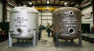
Which Materials Suit Make-Up Water Service?
How Big Should Make-Up Water Tanks Be?
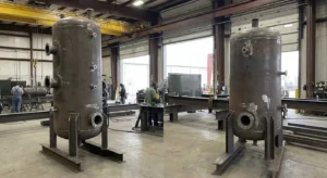
When to Spec Equalization Tanks for Industrial Systems
How Do Equalization Tanks Balance Flow?
What Is an Equalization Tank?
No related articles found.
About Author