Pump starts, stops, and speed changes in liquid pipelines create pressure waves that can spike or drop hundreds of psi, causing a water hammer that damages pumps, valves, and piping. This guide is for engineers, facility managers, and data center operators responsible for system reliability. You’ll learn how surge tanks work, how they differ from expansion and buffer tanks, how they’re sized, and what ASME requirements apply.
What Is a Surge Tank and What Does It Do?
A surge tank is a pressure vessel connected to a pipeline or process system that absorbs sudden pressure changes caused by rapid flow velocity changes. Unlike buffer tanks which add hydraulic volume to prevent chiller short cycling or expansion tanks which accommodate thermal volume changes in closed loops, surge tanks are specifically designed to handle the dynamic pressure transients that occur when flow is rapidly started, stopped, or redirected.
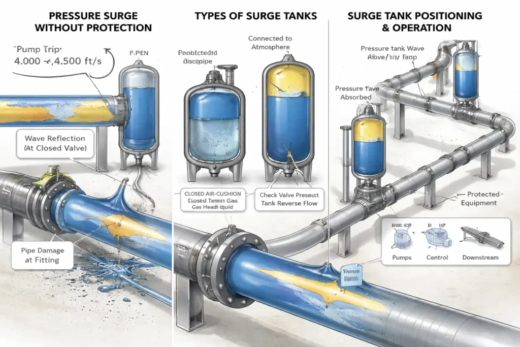
The fundamental problem surge tanks solve is water hammer, the phenomenon that occurs when a moving column of liquid is suddenly decelerated. When a pump trips offline, a valve closes quickly, or a pipe ruptures downstream, the kinetic energy of the moving liquid converts to pressure energy instantaneously. This pressure spike the water hammer travels back through the pipeline as a compression wave, reflecting off closed valves, pipe bends, and diameter changes. Without a pressure relief pathway, these waves add and amplify, reaching pressures that exceed the pipeline’s design rating.
A surge tank connected to the pipeline provides an open volume that the pressure wave can expand into dissipating its energy as the liquid surface in the tank rises and falls rather than transmitting the full pressure spike to vulnerable equipment downstream.
Surge tanks operating above 15 psig are classified as pressure vessels under ASME Section VIII Division 1 and must be fabricated and inspected to the applicable requirements.
How Surge Tanks Prevent Water Hammer and Pressure Transients
Water hammer occurs when the momentum of a moving liquid column is arrested faster than the pipeline system can accommodate. The severity of the pressure spike depends on the flow velocity, the fluid density, the speed of sound in the fluid, and how quickly the flow change occurs. The Joukowsky equation quantifies this relationship:
ΔP = ρ × a × ΔV
Where:
- ΔP = pressure surge in Pa or psi
- ρ = fluid density in kg/m³ or lb/ft³
- a = wave speed (speed of sound in the fluid) in m/s or ft/s
- ΔV = change in flow velocity in m/s or ft/s
For water at typical industrial temperatures, the wave speed is approximately 4,000 to 4,500 ft/s. A sudden velocity change of just 1 ft/s produces a pressure spike of approximately 60 to 65 psi. In large industrial pipelines with flow velocities of 5 to 10 ft/s, pump trip events can produce pressure spikes of 300–650 psi above normal operating pressure well above the design rating of most process piping systems.
A surge tank connected to the pipeline at a strategic point provides a low-resistance pathway for the pressure wave to dissipate. As the wave front reaches the tank connection, the liquid rises into the tank converting the pressure energy of the wave into potential energy of the elevated liquid surface. The liquid then drains back into the pipeline as the wave subsides, restoring normal operating conditions without transmitting the spike to downstream equipment.
The National Board of Boiler and Pressure Vessel Inspectors maintains registration records and inspection guidance for ASME-certified pressure vessels used in surge protection applications.
Surge Tanks vs Buffer Tanks vs Expansion Tanks
All three vessel types are pressure vessels used in liquid systems, but they address entirely different problems and are sized using entirely different methods.
| Factor | Surge Tank | Buffer Tank | Expansion Tank |
| Primary purpose | Absorb pressure transients | Prevent chiller short cycling | Control thermal pressure changes |
| Trigger event | Rapid flow velocity change | Low cooling load vs chiller output | Temperature change in closed loop |
| Response time | Milliseconds | Minutes | Hours |
| Contains | Liquid with gas headspace or open surface | Water only | Gas cushion + water |
| Sizing basis | Pipeline flow velocity and wave speed | 10 gal/ton chiller capacity | System volume × expansion coefficient |
| Typical location | Pipeline high points, pump discharge, valve stations | Primary chiller loop | Closed loop high point or mechanical room |
| ASME required | Yes, above 15 psig | Yes, above 15 psig | Yes, above 15 psig |
Understanding these distinctions is essential for correct system specification. A data center chilled water plant may require all three a buffer tank to protect chillers from short cycling, an expansion tank to manage thermal pressure changes, and a surge tank to protect pump discharge piping from water hammer during emergency shutdowns or power failures.
Types of Surge Tanks Used in Industrial Applications
Three surge tank configurations are used in industrial and process applications depending on the system pressure, pipeline geometry, and severity of the expected transient.
Open surge tanks
Also called open standpipes are unpressurized vessels open to the atmosphere at the top and connected to the pipeline. They are installed at or above the hydraulic grade line of the system. When a pressure transient reaches the tank connection, the liquid rises into the standpipe. The height of the liquid column absorbing the pressure energy. Open surge tanks are simple, reliable, and require no gas pre-charge maintenance, but they are limited to systems where the surge pressure does not exceed atmospheric plus the liquid head in the tank.
Air-cushion surge tanks
Also called closed surge tanks or air vessels are pressurized vessels containing both liquid and a compressed air or nitrogen cushion. The gas cushion provides additional pressure buffering capacity beyond what the liquid column alone can provide. Air-cushion tanks are used in systems where open tanks would need to be impractically tall to absorb the expected surge pressure, or where the system operates at pressures that preclude open connections to the atmosphere. These tanks require periodic inspection of gas volume and pressure, and are subject to ASME Section VIII requirements when operating above 15 psig.
One-way surge tanks
Also called one-way check surge tanks use a check valve on the tank connection that allows liquid to flow from the tank into the pipeline but prevents reverse flow. These are used specifically to prevent column separation, a condition where the pipeline pressure drops below the liquid vapor pressure and the liquid column separates, creating a vacuum that collapses violently when pressure is restored. One-way surge tanks inject liquid into the low-pressure zone immediately after column separation begins, preventing the vacuum collapse that produces the most damaging secondary surge.
For modular process skid packages that integrate surge tanks with pumps, valves, and controls in a pre-engineered assembly, Red River designs the full surge protection configuration before fabrication begins.
Sizing Surge Tanks for Industrial Applications
Surge tank sizing is based on transient hydraulic analysis, which simulates pressure wave behavior throughout the pipeline to determine maximum and minimum pressures during surge events and the protection required to keep them within safe limits.
Key sizing factors include:
- Flow velocity: Higher velocities create larger pressure spikes, increasing surge tank requirements.
- Pump characteristics: Pump and motor inertia affect how quickly flow decelerates after shutdown, influencing surge severity.
- Pipeline profile: High points are prone to column separation and may require dedicated surge protection.
- Valve closure time: Fast-closing valves (below critical closure time 2L/a) generate full water hammer.
- System pressure: Determines whether open or pressurized surge tanks are required.
For pressure vessel fabrication sized to each project’s surge analysis results, Red River works with project engineers to validate tank volume, connection location, and ASME pressure rating before fabrication begins.
Material Selection for Surge Tanks
Surge tank material selection depends on fluid chemistry, temperature, and corrosion risk, typically choosing between carbon steel and stainless steel.
Carbon steel (e.g., SA-516 Gr. 70, SA-285 Gr. C) with internal epoxy lining is standard for clean water and controlled cooling systems. Stainless steel (304L or 316L) is used for corrosive service, high chlorides, or aggressive glycol mixtures where long-term corrosion resistance is critical.
For detailed guidance on which materials suit chilled water service and how material selection affects long-term surge tank performance, Red River evaluates each project’s fluid chemistry before recommending a specification.
ASME Certification for Surge Tanks
Surge tanks operating above 15 psig are ASME Section VIII Division 1 pressure vessels and must meet strict design, fabrication, and testing requirements.
Certification requirements include:
- Design verification: Shell thickness based on ASME Section II material allowables and vessel geometry, including gas cushion pressure in air-cushion tanks
- Hydrostatic testing: Vessel tested at 1.3× MAWP with an Authorized Inspector witnessing and approving results
- Material traceability: CMTRs confirm all pressure parts meet specified ASME grades and provide full mill-to-fabrication traceability
- Final documentation: Form U-1 submission and U-stamp authorization before the vessel can be placed in service
For a complete overview of ASME code stamped pressure vessel requirements including documentation standards, Red River provides full certification packages with every fabricated surge tank.
The American Society of Mechanical Engineers publishes BPVC Section VIII Division 1 governing design, fabrication, and testing requirements for surge tanks operating above 15 psig.
Surge Tanks as the Pressure Safety Foundation of Industrial Pipelines
Water hammer is not a minor operational inconvenience, it is a structural loading event that occurs in milliseconds and can exceed the design pressure of pipeline components by a factor of two or more. These tanks do not reduce the energy of the pressure wave, they redirect it into a controlled volume where it can dissipate without damaging equipment.
Correctly sized and located, this equipment is one of the most cost-effective infrastructure investments in a large pipeline system protecting pumps, valves, and pipe fittings that cost orders of magnitude more than the surge protection vessel itself. Incorrectly sized, incorrectly located, or omitted entirely, the cost of a single water hammer event in equipment damage, unplanned downtime, and emergency repair typically exceeds the capital cost of the surge tank many times over.
Red River’s engineering team reviews pipeline hydraulic data and surge analysis results during the specification phase to confirm tank volume, location, and pressure rating before fabrication begins ensuring the vessel solves the problem it was specified to solve.
Need a Reliable Partner?
Red River fabricates ASME U-stamp certified surge tanks for industrial pipelines, process systems, and data center cooling infrastructure sized to each project’s transient hydraulic analysis results and configured for the specific surge event, fluid chemistry, and pressure rating required.
Every tank includes full material traceability, certified weld documentation, hydrostatic test records, and Form U-1. Contact our team to discuss surge tank fabrication for your project.
Frequently Asked Questions
1. What causes pressure surge in cooling loops?
Pressure surges in cooling loops are caused by rapid flow velocity changes, pump trips, fast-closing valves, or sudden load changes that decelerate the moving liquid column and convert its kinetic energy into a pressure spike.
2. How do surge tanks protect pumps and valves?
Surge tanks provide a low-resistance volume that pressure waves can expand into before reaching pumps, valves, and fittings. When a pressure transient reaches the tank connection, liquid rises into the tank absorbing the wave energy rather than transmitting the full pressure spike to downstream equipment. .
3. Which NDE methods apply to surge tanks?
ASME Section VIII requires visual inspection of all welds during fabrication, radiographic testing (RT) or ultrasonic testing (UT) of seam welds based on the specified joint efficiency, and hydrostatic testing at 1.3× MAWP before the U-stamp is applied.
4. What is column separation?
Column separation occurs when pipeline pressure drops below the liquid’s vapor pressure the liquid vaporizes locally and the column splits. When pressure is restored, the two column sections collide violently, producing a secondary surge more damaging than the original water hammer.
5. Does every surge tank require ASME certification?
Yes, when operating above 15 psig. Air-cushion surge tanks are pressurized vessels under ASME Section VIII Division 1. Open surge tanks connected to the atmosphere at pressures below 15 psig may fall outside ASME jurisdiction but local regulatory requirements should be confirmed before specifying an open configuration.
Key Takeaways
- Surge tanks are required for millisecond-scale water hammer protection in high-energy pipeline systems.
- Proper sizing depends on transient hydraulic analysis, not static volume rules.
- Incorrect location or sizing eliminates protection even if the tank is properly built.
- ASME Section VIII compliance (RT/UT + hydrotest + U-stamp) is mandatory above 15 psig.
- Surge tanks are most effective when integrated early in system design, not added after failures.
Related Blog Post
How Do You Size Thermal Storage for Data Centers?
Thermal Storage Tank Design Engineering
About Author