Chillers that cycle on and off repeatedly wear out faster, consume more energy per ton of cooling produced, and create temperature instability that affects sensitive equipment. Buffer tanks solve this by adding hydraulic volume to the chilled water loop giving the system the thermal mass it needs to absorb demand fluctuations and keep chillers running at stable, efficient operating points. This guide covers how buffer tanks work, how they are sized and tested, how they differ from chilled water storage tanks, and how they integrate into data center and industrial cooling systems.
What Is a Buffer Tank and What Does It Do?
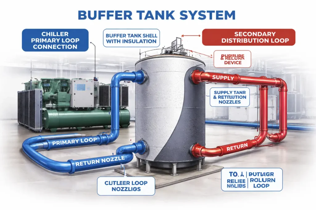
A buffer tank is an insulated pressure vessel connected to a chilled water loop that provides additional water volume between the chiller and the distribution system. It does not store hours of cooling reserve like a chilled water storage tank instead it holds minutes of reserve specifically designed to prevent chiller short cycling and absorb short-duration demand spikes.
The primary function of a buffer tank is hydraulic decoupling. In systems where the chiller’s minimum cooling output exceeds the building’s minimum cooling load, the chiller satisfies the load quickly, shuts off, and restarts again within minutes. Each start-stop cycle stresses the compressor, increases refrigerant wear, and reduces overall system efficiency. A buffer tank breaks this cycle by providing enough additional water volume that the chiller can run for a longer period before the return water temperature drops to the cutoff setpoint.
These vessels also stabilize flow in variable-speed pump systems where flow rates change frequently in response to varying zone demand. Rapid flow changes create pressure transients that cause pump cavitation, control valve hunting, and inconsistent supply temperatures at end-use equipment. The buffer tank acts as a hydraulic separator isolating the primary chiller loop from the secondary distribution loop and allowing each to operate at its own flow rate independently.
Buffer tanks used in pressurized chilled water systems above 15 psig are classified as pressure vessels under ASME Section VIII and must be fabricated and inspected to the applicable division requirements.
How Buffer Tanks Prevent Chiller Short Cycling
Chiller short cycling occurs when the system water volume is insufficient to absorb the chiller’s minimum output before return water temperature drops to the cutoff point. The chiller satisfies the load, shuts off, the return water warms slightly, and the chiller restarts sometimes within 2–5 minutes of shutting down.
Each compressor start draws a large inrush current and creates a pressure shock in the refrigeration circuit. Manufacturers typically specify minimum off-times of 10–20 minutes between starts to protect the compressor and allow refrigerant pressures to equalize. Systems that cannot maintain this minimum off-time experience accelerated compressor wear, higher maintenance costs, and shorter equipment life.
The buffer tank prevents short cycling by increasing the total system water volume. A larger water volume takes longer to change temperature giving the chiller time to complete a full, efficient run cycle before the return water temperature triggers a restart. The relationship between buffer volume and cycle time is direct: doubling the buffer volume approximately doubles the minimum cycle time at the same load conditions.
For chilled water system design in data centers and industrial facilities, Red River sizes buffer tanks against the chiller’s minimum output, the system’s minimum load, and the required minimum cycle time to protect the equipment.
For reference data on minimum chiller cycle times and system volume requirements, see the ASHRAE HVAC Systems and Equipment guide.
Buffer Tank Sizing The 10 Gallon Rule and When to Deviate
The most widely used rule of thumb for buffer tank sizing is 10 gallons per ton of installed chiller capacity. For a 200-ton chiller, this produces a 2,000-gallon buffer tank. This rule provides approximately 10 minutes of cycle time at minimum load conditions in most standard chilled water system configurations.
However, this rule is a starting point not a universal specification. Several factors justify deviation:
Chiller minimum load percentage: chillers with higher minimum load percentages (some variable-speed chillers go as low as 10% of rated capacity) require more buffer volume than chillers with higher minimum thresholds. Lower minimum load means the chiller can satisfy the load more quickly, requiring more buffer volume to extend the cycle time.
System minimum load: facilities with very low minimum cooling loads such as data centers with variable IT loads or industrial plants with shift-based production experience more short cycling risk than facilities with consistently high base loads. Higher short cycling risk requires more buffer volume.
Multiple chiller configuration: systems with multiple chillers in parallel must buffer against the minimum output of the smallest chiller stage that can be brought online. Staging strategies affect how much buffer volume is needed between stages.
Variable flow primary systems: in systems where primary loop flow varies, the buffer tank must handle a wider range of hydraulic conditions. Sizing for the worst-case low-flow condition prevents cavitation and flow starvation at the chiller.
For precise sizing calculations, engineers reference the system’s load profile, chiller performance curves, and minimum cycle time requirements. Red River works with project engineers during the specification phase to validate buffer volume against these parameters before fabrication begins.
Buffer Tanks vs Chilled Water Storage Tanks
These two tank types are frequently confused because they serve adjacent functions in the same system. Understanding the distinction is essential for correct specification.
| Factor | Buffer Tank | Chilled Water Storage Tank |
| Primary purpose | Prevent short cycling | Load shifting and demand charge reduction |
| Reserve duration | Minutes (1–10 min) | Hours (2–8 hrs) |
| Sizing basis | 10 gal/ton chiller capacity | Peak load × discharge hours ÷ (500 × delta-T) |
| Energy strategy | Hydraulic stability | Off-peak chilling, peak demand reduction |
| System location | Primary loop, close to chiller | Parallel to distribution loop |
| Typical volume | 500–5,000 gallons | 10,000–500,000+ gallons |
Both tank types are often used together in large cooling systems. The buffer tank handles short-duration hydraulic transients and protects the chiller from short cycling. The chilled water storage tank provides sustained thermal reserve for load shifting and peak demand charge reduction. Understanding how much volume is needed for chilled water storage versus buffer volume requires evaluating both functions separately before combining them in a single tank specification.
Which Tests Verify Buffer Tank Quality?
Buffer tanks operating above 15 psig as ASME pressure vessels must pass a defined set of fabrication and inspection tests before entering service. These tests verify structural integrity, weld quality, and leak-free performance under operating conditions.
Hydrostatic testing is the primary pressure test required by ASME Section VIII Division 1. The tank is filled with water and pressurized to 1.3 times the maximum allowable working pressure (MAWP). This test verifies that the shell, heads, welds, and nozzle connections can withstand design pressure with the required safety margin. An Authorized Inspector witnesses the test and signs off on the result before the U-stamp is applied.
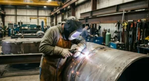
Weld inspection is performed throughout fabrication, not just at final testing. Visual inspection, radiographic testing (RT), and ultrasonic testing (UT) verify weld quality at seams, nozzle attachments, and support connections. The extent of weld examination required depends on the joint efficiency specified in the design full radiography achieves a joint efficiency of 1.0, while spot examination reduces this to 0.85.
Leak testing confirms that all connections, nozzle welds, and access point closures are free of leaks at operating pressure. This is typically performed after hydrostatic testing as a final verification step.
Material documentation while not a physical test, ASME requires that all pressure-containing materials be accompanied by certified material test reports (CMTRs) that verify chemical composition and mechanical properties match the specified ASME grade. Red River maintains full material traceability from mill certification through final documentation.
For a complete overview of ASME certification requirements, see ASME code stamped pressure vessels.
The National Board of Boiler and Pressure Vessel Inspectors maintains a registry of ASME-certified vessels and authorized inspection agencies.
Material Selection for Buffer Tanks in Chilled Water Service
Buffer tank material selection follows the same logic as chilled water storage tank material selection the choice between carbon steel and stainless steel depends on water chemistry, glycol concentration, and inhibitor maintenance reliability.
Carbon steel with internal lining is the standard specification for most buffer tanks in standard treated water systems. ASME grades SA-516 Grade 70 and SA-285 Grade C are the most commonly specified grades. Internal epoxy lining protects the steel substrate from corrosion in properly maintained systems. Coal tar epoxy is specified where water treatment chemistry is more aggressive.
Stainless steel grades 304L and 316L are specified when glycol concentrations exceed 40%, when water purity requirements preclude chemical inhibitors, or when chloride exposure creates elevated corrosion risk. The cost premium over carbon steel is justified when the consequence of early tank failure system contamination, unplanned downtime, and tank replacement exceeds the upfront material cost difference.
For detailed guidance on which materials suit chilled water service, Red River evaluates each project’s water chemistry and operating conditions before recommending a specification.
Buffer Tanks in Data Center Cooling Systems
Data centers present specific buffer tank challenges that differ from standard commercial cooling applications. Server loads fluctuate rapidly a batch computing job or a surge in virtual machine activity can spike cooling demand by 20–30% within seconds. Standard chilled water loops without buffering cannot respond fast enough, causing supply temperature to rise and triggering thermal throttling in servers.
These tanks provide the hydraulic volume needed to absorb these rapid load changes while chillers and cooling tower fans respond at their mechanical rate of change. The buffer tank effectively buys the system 5–15 minutes of response time enough for chillers to ramp up, cooling towers to adjust fan speed, and control sequences to stabilize supply temperature.
What size buffer tank for a data center depends on the facility’s IT load variability, the chiller’s minimum load percentage, and the required supply temperature stability at the server inlet. A hyperscale data center with highly variable workloads and tight temperature requirements needs more buffer volume than a colocation facility with more predictable load patterns.
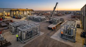
Red River fabricates buffer tanks for data center applications with the nozzle configurations, support structures, and access provisions that integration into modular cooling infrastructure requires. Contact our team to discuss buffer tank specifications for your data center project.
Need a Reliable Partner?
Red River designs and fabricates ASME U-stamp certified buffer tanks for chilled water systems in data centers, industrial facilities, pharmaceutical plants, and large commercial cooling applications. Every tank is sized to the project’s specific chiller configuration, load profile, and minimum cycle time requirements with full material traceability, certified weld documentation, and hydrostatic test records included as standard. Contact our team to discuss your buffer tank requirements.
Buffer Tanks as the Foundation of Chilled Water System Stability
A chilled water system without adequate buffer volume is a system that forces its most expensive and most maintenance-intensive component the chiller to operate outside its design envelope. Short cycling, pressure transients, and flow instability are not inevitable features of chilled water systems. They are engineering problems with a straightforward solution.
Buffer tanks provide the hydraulic volume that allows chillers to run at steady, efficient operating points, pumps to deliver consistent flow without cavitation, and control systems to maintain stable supply temperatures across varying load conditions. Sized correctly, specified with the right materials, and fabricated to ASME standards, a buffer tank is one of the highest-return investments in a chilled water system reducing maintenance costs, extending equipment life, and improving the consistency of cooling delivery across the facility’s service life.
Frequently Asked Questions
1. How do buffer tanks prevent chiller short cycling?
Buffer tanks increase total system water volume, slowing the rate of temperature change in the loop. This gives the chiller time to complete a full run cycle before return water temperature drops to the cutoff setpoint preventing the rapid start-stop cycles that wear out compressors and reduce system efficiency.
2. What size buffer tank for data centers?
A common starting point is 10 gallons per ton of installed chiller capacity. Data centers with highly variable IT loads or tight supply temperature requirements may need more volume. Sizing should be validated against the chiller’s minimum load percentage and the facility’s peak load variability before specifying.
3. Which tests verify buffer tank quality?
ASME Section VIII Division 1 requires hydrostatic testing at 1.3× MAWP, weld inspection throughout fabrication, and leak testing at operating pressure. An Authorized Inspector must witness key stages and sign off on the Manufacturer’s Data Report (Form U-1) before the U-stamp is applied.
4. What causes chiller short cycling and how does a buffer tank fix it?
Short cycling occurs when the system water volume is too small to absorb the chiller’s minimum output the chiller satisfies the load too quickly, shuts off, and restarts within minutes. A buffer tank increases total system volume, slowing the rate of temperature change and giving the chiller time to complete a full efficient run cycle before the return water temperature triggers a restart.
5. What material is used for buffer tanks in chilled water service?
Carbon steel grade SA-516-70 with internal epoxy lining suits most standard applications. Stainless steel 304L or 316L is specified when glycol concentrations exceed 40%, when chloride exposure is present, or when water purity requirements preclude chemical inhibitors.
6. Does ASME certification apply to buffer tanks?
Yes, when the buffer tank operates above 15 psig. Most closed-loop chilled water systems operate between 20–150 psig, placing buffer tanks under ASME Section VIII Division 1 requirements. Red River fabricates U-stamp certified buffer tanks with full documentation.
7. What size buffer tank does a data center need?
Data center buffer tank sizing depends on IT load variability, chiller minimum load percentage, and required supply temperature stability. Facilities with highly variable workloads and tight temperature requirements need more buffer volume than those with predictable load patterns. Red River evaluates these parameters during the specification phase.
Key Takeaways
- Buffer tanks add hydraulic volume to chilled water loops to prevent chiller short cycling the 10 gallons per ton rule provides a starting point, but actual sizing must be validated against the chiller’s minimum load percentage and system minimum cooling demand.
- Buffer tanks differ from chilled water storage tanks in purpose and scale buffer tanks hold minutes of reserve for hydraulic stability while storage tanks hold hours of reserve for load shifting and demand charge reduction.
- Chiller short cycling occurs when system water volume is too small to absorb the chiller’s minimum output each start-stop cycle stresses the compressor, increases refrigerant wear, and reduces COP across the operating year.
- ASME Section VIII Division 1 requires hydrostatic testing at 1.3× MAWP, weld inspection throughout fabrication, and Authorized Inspector sign-off on Form U-1 before the U-stamp is applied.
- Carbon steel SA-516-70 with internal epoxy lining suits most standard chilled water buffer tank applications stainless steel 304L or 316L is required when glycol concentrations exceed 40% or chloride exposure creates elevated corrosion risk.
- Data center buffer tanks must absorb rapid IT load fluctuations while chillers respond at their mechanical rate of change sizing for IT load variability and supply temperature stability requirements is critical for data center applications.
Related Blog Post
Where Should Industrial Tanks Be Located?
How Do Tie-Ins Impact Downtime
What Are Thermal Storage Tank Design Parameters?
Can Modularization Speed Builds on Industrial Projects?
Which Weld Procedures Are Common in Vessel Fabrication
About Author